Resonant orifice type electronically controlled fuel injector

An electronically controlled fuel injection and fuel injector technology, which is applied to fuel injection devices, machines/engines, and charging systems, can solve the problems of large dynamic oil return and energy loss, reduce fuel pressure fluctuations, improve Effect of pressure fluctuation and economical improvement

Active Publication Date: 2022-08-02
HARBIN ENG UNIV
View PDF0 Cites 0 Cited by
  • Summary
  • Abstract
  • Description
  • Claims
  • Application Information

AI Technical Summary

Problems solved by technology

This part of high-pressure fuel is pressurized by the oil pump, but it returns directly to the fuel tank without doing work. The dynamic oil return is large, resulting in energy loss

Method used


Image

  • Resonant orifice type electronically controlled fuel injector
  • Resonant orifice type electronically controlled fuel injector
  • Resonant orifice type electronically controlled fuel injector

Examples


Embodiment Construction

[0021] The present invention will be described in more detail below in conjunction with the accompanying drawings:

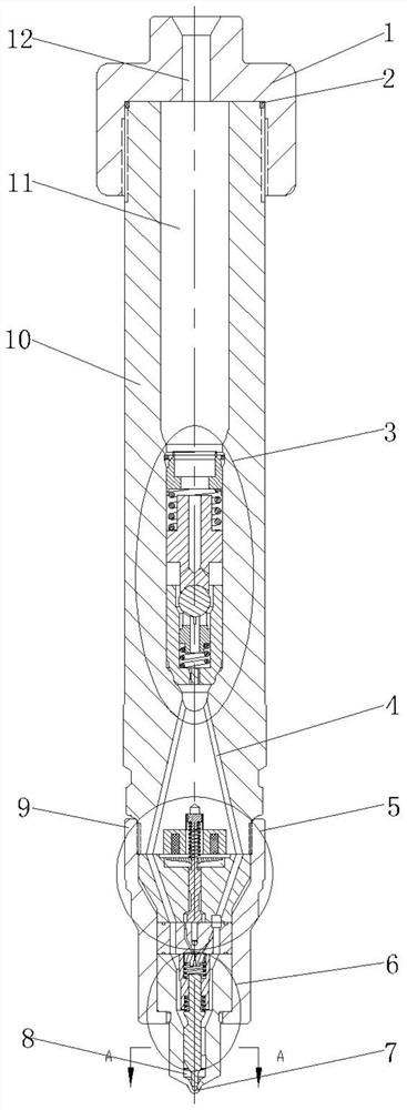
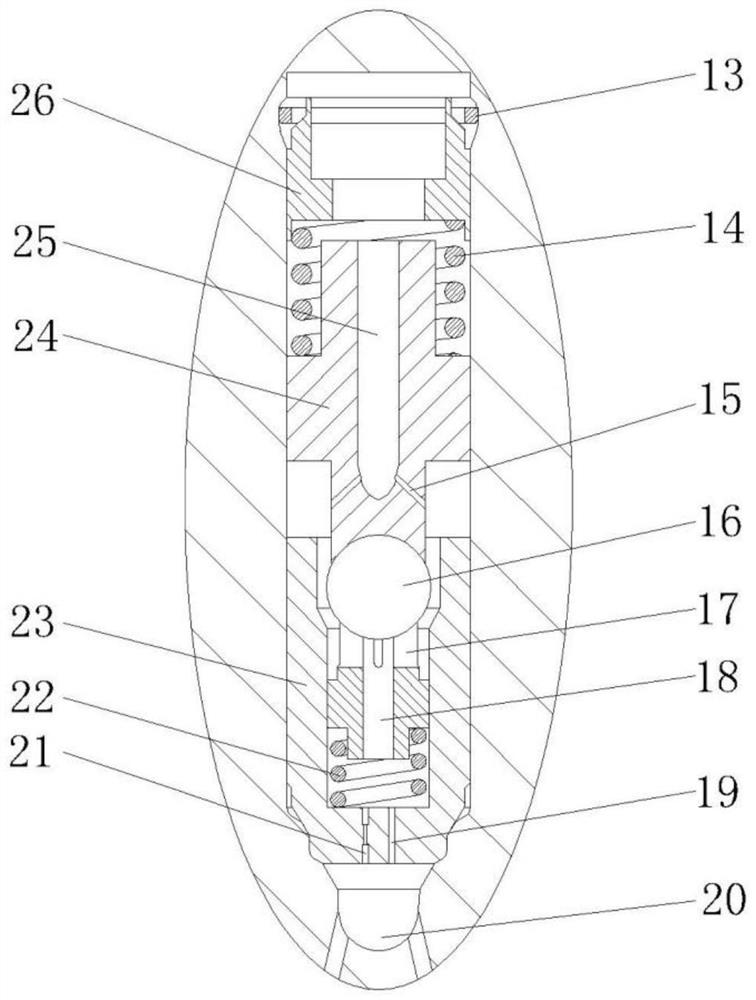
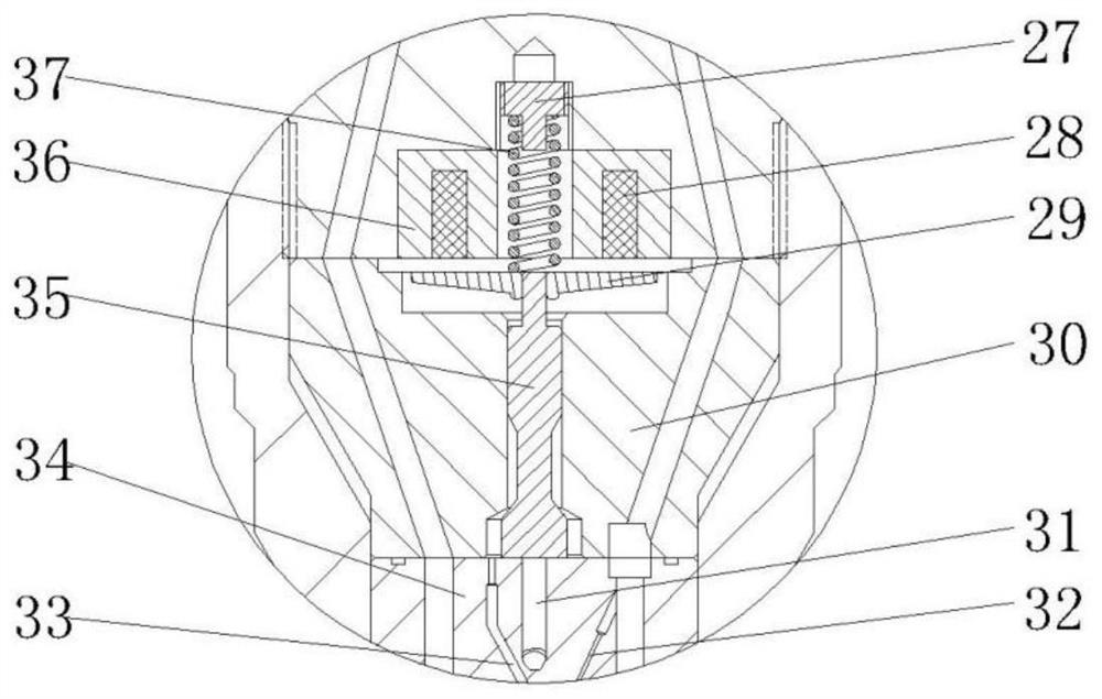
[0022] combine Figure 1-5 , The present invention includes an injector head 1 , a restrictor valve assembly 3 , a solenoid valve assembly 5 , a needle valve assembly 6 , a tight cap 9 , and an injector body 10 . The fuel injector head 1 is mounted on the fuel injector body 10 through a fitting connection with threads, and is sealed by a sealing ring 2 placed on the fuel injector body 10 . A main oil inlet hole 12 is provided in the injector head 1 and communicates with the pressure accumulating chamber 11 in the injector body 10 . A restrictor valve assembly 3 is provided below the pressure accumulating chamber 11 . The restrictor valve assembly 3 is installed inside the injector body 10, and its main structure includes a retaining ring 13, a damping spring 14, a ball valve 16, a support control slider 17, a ball valve return spring 22, a ball valve return sp...


PUM


Abstract

The purpose of the present invention is to provide a resonant orifice type electronically controlled fuel injector, which includes a fuel injector body, a restrictor valve assembly, a solenoid valve assembly, and a needle valve assembly. There is a pressure accumulating cavity in the fuel injector body, which is connected with the main oil inlet hole and the restrictor valve assembly to ensure the stability of the fuel injection process of each cylinder when the fuel is injected with a large pulse width. The restrictor valve assembly is installed under the accumulator chamber to avoid abnormal continuous fuel injection. A resonance through hole and a resonance throttle hole are processed at the bottom of the restrictor valve assembly, which effectively reduces the fluctuation of the fuel passing through the restrictor valve assembly. The solenoid valve assembly processed at the bottom of the injector body is driven by the electromagnetic force to move the valve stem, which can realize a flexible fuel injection strategy and a fuel injection process with fast response and high control precision. Through the orifice plate orifice and the two-way oil inlet of the annular side oil circuit, the pressure building process of the control chamber is accelerated, and the response speed of the needle valve seating is improved. The orifice plate structure processed in the needle valve assembly effectively reduces the dynamic oil return during the injection process and realizes the characteristics of micro-dynamic oil return.

Description

technical field [0001] The invention relates to an engine fuel injection device, in particular to a high pressure common rail fuel injection device. Background technique [0002] At present, the market has begun to gradually adopt high-speed solenoid valve fuel injectors to meet the latest emission regulations. The outstanding feature of this electronically controlled injector is that it uses the electrical signal output by the electronic control unit to control the high-speed solenoid valve to achieve flexible fuel injection rules. The injector with high-speed solenoid valve has fast system response, high control precision and the ability to inject multiple times. However, this electronically controlled fuel injector also has areas that need to be improved: during the fuel injection process, there is always high-pressure fuel flowing through the inlet and outlet orifices. This part of high-pressure fuel is pressurized by the oil pump, but returns directly to the fuel tank...

Claims


Application Information

Patent Timeline
Patent Type & Authority Patents(China)
IPC IPC(8): F02M47/02F02M61/10F02M61/18F02M63/00
CPCF02M47/027F02M61/10F02M61/1893F02M63/0017F02M63/0035F02M63/0036F02M63/007
Inventor 范立云张孝勇费红姿姚崇
Owner HARBIN ENG UNIV
Why Eureka
Try Eureka