Rotor pump and shaft sealing device thereof

A shaft seal and rotor pump technology, which is applied in the direction of rotary piston pumps, pumps, rotary piston/swing piston pump components, etc. Problems such as the elasticity of the pressure spring can be improved to improve the shaft sealing performance, improve the service life and prolong the service life.

Inactive Publication Date: 2017-08-18
宁波邦威泵业有限公司
View PDF9 Cites 5 Cited by
  • Summary
  • Abstract
  • Description
  • Claims
  • Application Information

AI Technical Summary

Problems solved by technology

[0004] Although the solution proposed in the patent application No. 201610917398.4 has made great technical progress compared with the traditional rotor pump shaft sealing device, the inventor of this case found that when the rotor pump using this solution is used for conveying high-viscosity materials for a long time, Especially for materials that are easy to peel and agglomerate, agglomerated materials will still accumulate on the moving ring seat and the compression spring, which will affect the elasticity of the compression spring, thereby affecting the shaft seal performance of the rotor pump and the service life of the shaft seal

Method used


Image

  • Rotor pump and shaft sealing device thereof
  • Rotor pump and shaft sealing device thereof
  • Rotor pump and shaft sealing device thereof

Examples


Embodiment 1

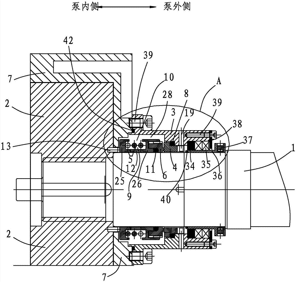
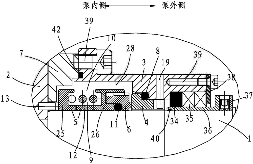
[0042] Such as figure 1 As shown, a shaft sealing device of a rotor pump, the shaft 1 of the rotor pump is fixedly connected with the impeller 2 as the rotor, and the shaft sealing device includes a mechanical seal seat 3, a stationary ring 4, a moving ring seat 5 and its The driving moving ring 6 is cylindrical and is set outside the shaft 1; the mechanical seal seat 3 is set outside the moving ring seat 5 and is fixedly connected with the pump body 7. The mechanical seal seat 3 includes a material section and an un The sealing section that allows material to enter, the inner diameter of the material section is larger than the inner diameter of the sealing section. The static ring 4 is located in the inner cavity of the sealing section of the mechanical seal seat 3 close to the material section, is directly sleeved on the outside of the shaft 1, and is connected with the mechanical seal seat 3 . Specifically, the following connection methods can be used: the machine seal sea...

Embodiment 2

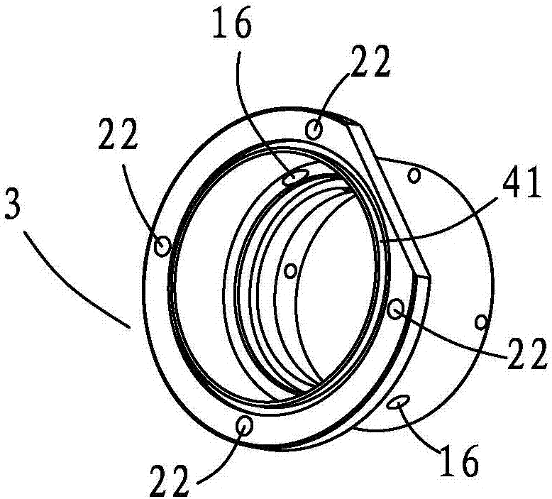
[0056] Such as Figure 16 , Figure 23 As shown, in this embodiment, on the basis of Embodiment 1, the material section and the sealing section of the mechanical seal seat 3 are separately set as the mechanical seal front seat 43 and the mechanical seal rear seat 44, and the mechanical seal seat 3 is composed of the mechanical seal front seat 43 The assembly assembled with the mechanical seal back seat 44, the inner side of the pump of the mechanical seal front seat 43 is provided with a flange end, and a plurality of connecting holes 22 are opened along the circumference of the flange end, the inner cavity of the pump body 7 is provided with a flange installation cavity, and the mechanical seal The flange end of the front seat 43 is embedded in the flange installation cavity, and the machine seal seat 3 is fixedly connected with the pump body 7 through a plurality of bolts 39 from the inner cavity of the pump body 7, and the flange end of the front seat 43 of the machine seal...


PUM


Abstract

The invention provides a shaft sealing device of a rotor pump. The shaft sealing device comprises a machine seal base (3), a fixed ring (4), a movable ring base (5) and a movable ring (6) driven by the movable ring base (5). A first O-shaped ring (8) is arranged at the gap position between the fixed ring (4) and the machine seal base (3). A cavity (28) is formed between the movable ring base (5) and the machine seal base (3). The movable ring base (5) is composed of a movable ring front base (25) and a movable ring rear base (26). An outer ring (30) and an inner ring (31) which protrude in the opposite directions are arranged on each of the movable ring front base (25) and the movable ring rear base (26), a movable ring base inner cavity (9) is defined, and the respective inner rings (31) are matched in a mutually concave-convex manner. A second O-shaped ring (11) is arranged on the pump inner side of the movable ring (6). A pressed spring (12) is arranged in the movable ring base inner cavity (9). The movable ring (6) is closely attached to the fixed ring (4). The movable ring base (5) is connected with an impeller (2) through at least one transmission pin (13), one ends of the transmission pins (13) are in close-fitting connection, and the other ends of the transmission pins (13) are in floating type insertion. By means of the shaft sealing device, the shaft sealing performance of the rotor pump can be effectively improved, and the service life of the rotor pump can be effectively prolonged.

Description

technical field [0001] The invention relates to a rotor pump, especially its shaft sealing device. Background technique [0002] Rotor pumps are also called colloid pumps, impeller pumps, universal delivery pumps, etc. Because their impellers are shaped like cams, they are also called cam pumps. Rotor pumps are positive displacement pumps; they are generally double rotors. The rotor pump achieves the purpose of conveying fluid materials by means of the periodic conversion of multiple fixed volume delivery units in the working chamber. Usually, a pair of synchronous gears are driven by a motor to drive the main and auxiliary shafts, and the double rotors are driven by the main and auxiliary shafts to rotate synchronously and in opposite directions, so that the volume of the pump changes, thereby forming a higher vacuum degree and discharge pressure; inlet It is a low-pressure area, and the outlet is a high-pressure area. The rotary lobe pump is mainly used for the transport...

Claims


Application Information

Patent Timeline
Patent Type & Authority Applications(China)
IPC IPC(8): F04C15/00F04C2/12
CPCF04C15/0023F04C2/126F04C15/0042
Inventor 谭在良
Owner 宁波邦威泵业有限公司
Why Eureka
Try Eureka