Unlock instant, AI-driven research and patent intelligence for your innovation.

Method for crane turning drive

A crane and driven technology, which is applied in the direction of cranes, trolley cranes, traveling mechanisms, etc., can solve the problems of crane manufacturing and maintenance costs, crane structure complexity, etc., and achieve the effect of cost saving

Inactive Publication Date: 2017-08-18
KONECRANES GLOBAL
View PDF15 Cites 1 Cited by
  • Summary
  • Abstract
  • Description
  • Claims
  • Application Information

AI Technical Summary

Problems solved by technology

[0010] For all the above-mentioned cranes, the intermediate position for the steering drive is particularly problematic, which complicates the construction of the crane and thus causes costs in the manufacture and maintenance of the crane

Method used


Image

  • Method for crane turning drive
  • Method for crane turning drive

Examples


Embodiment Construction

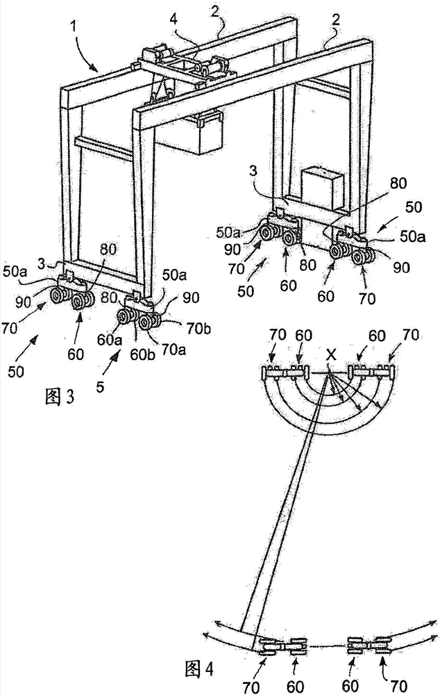
[0022] With reference to Figure 1, the figure shows a crane with a frame 1, which is provided in its upper part with a main support structure 2 formed by two upper beams 2, the frame 1 in its lower part in the frame The opposite side of the lower part of 1 is provided with lower beam structures 3 that are transverse to the main support structure 2 and parallel to each other. The trolley 4 is arranged for movement along the main support structure 2. The end of the lower beam structure 3 is provided with a supporting wheel structure 5, and each supporting wheel structure 5 includes two wheels 6 and 7 connected in series. In other words, a total of four supporting wheel structures 5 are provided, each in a lower corner of the crane 1. Therefore, there are a total of eight wheels 6 and 7.

[0023] In this example, the wheels 6 and 7 are mounted at the lower ends of the tubes 8 and 9 through bearings, and on the sides of these tubes, the tubes extend downward from the supporting whe...


PUM


Abstract

The invention relates to a method for turning drive of a crane, a rubber-tyred crane in particular, comprising a frame which has a main support structure in its upper part and lower beam structures transverse to the main support structure in the lower part of the frame, on opposite sides of the lower part of the frame; at least one rubber-tyred wheel or rubber-tyred wheel arrangement (6, 7) rotatable about a vertical axis at both ends of the lower beam structures, i.e. in each lower corner of the crane, whereby in turning drive the wheels or wheel arrangements (6, 7) of one lower beam structure are locked to a longitudinal drive position of the crane, i.e. parallel to the lower beam structure, the wheels or wheel arrangements (6, 7) of the other lower beam structure are turned and locked to a transverse drive position of the crane, i.e. transverse to the lower beam structure, and drive wheels or wheel arrangements (6) are driven at a speed proportional to their turning radius, the centre point (X) of the turning radius being at the centre point between the transverse wheels or wheel arrangements of the other lower beam structure.

Description

Technical field [0001] The present invention relates to a method for steering driving of a crane, in particular a crane with rubber tires, the crane comprising: a frame having a main support structure in its upper part and in the lower part of the frame The opposite side of the lower part of the frame is transverse to the lower beam structure of the main support structure; the pulley is arranged to move along the main support structure; at least one wheel with rubber tires or a wheel structure with rubber tires, the wheel or wheel structure can be Turn around the vertical axis at both ends of the lower beam structure, i.e. in each lower corner of the crane. Background technique [0002] Gantry cranes with rubber tires are used in the container storage field to arrange and handle cranes. There are many types and sizes of cranes, and most commonly, they are grouped according to the number of wheels in the crane, namely 4, 8 or 16 wheel cranes. They move on rubber tires along a st...

Claims


Application Information

Patent Timeline
IPC IPC(8): B66C9/04B66C19/00
CPCB66C9/04B66C19/007
Inventor E·奥加帕罗J·桑塔拉
Owner KONECRANES GLOBAL