Power assisting device for robot arm

A technology of a power assist device and a robot arm, which can be applied to claw arms, manipulators, manufacturing tools, etc., and can solve problems such as restricting the enlargement of heavy robots.

Pending Publication Date: 2017-08-22
范红兵
View PDF0 Cites 1 Cited by
  • Summary
  • Abstract
  • Description
  • Claims
  • Application Information

AI Technical Summary

Problems solved by technology

To a certain extent, it limits the enlargement of heavy-duty robots

Method used


Image

  • Power assisting device for robot arm
  • Power assisting device for robot arm
  • Power assisting device for robot arm

Examples


Embodiment 1

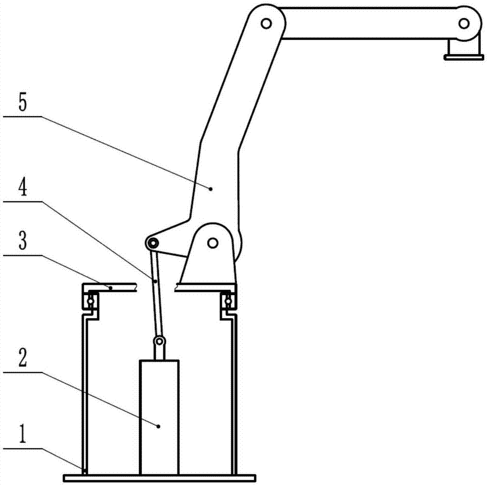
[0018] as shown in the picture 1 As shown, this example is a booster device for the first arm of the robot, which includes a booster power source (2) composed of a spring set arranged on the robot base (1), and an output end of the booster power source The connected rod-shaped transmission tool (4), the other end of the transmission tool is directly hinged with the robot arm (5).

[0019] During work, when the robot arm (5) swings outwards under the action of the load and performs a tilting action, the robot arm pulls the output end of the power assist power source (2) through the transmission (4) to lift upwards. At this time, the power assist power source (2) The spring in ) is compressed by force, and the transmission device (4) provides the robot arm with a reverse boost against the weight of the load. The more the robot arm swings outward, the more the booster power source (2) is compressed, and the greater the reaction force generated. This method can well meet the as...

Embodiment 2

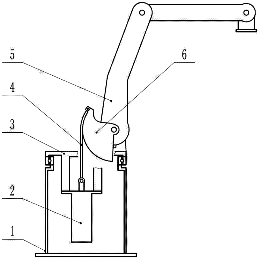
[0022] as shown in the picture 2 As shown, the other structure of this embodiment is the same as that of Embodiment 1, the difference is that: the booster power source (2) in this example is set on a one-axis rotating base (3) and rotates with the rotating base; the transmission (4) It is movably connected with the robot arm (5) through the transition block (6) fixed on the robot arm. The transition block (6) is designed with an arc-shaped outer edge; the transmission tool (4) is a flexible chain attached to the transition block ( 6) on the arc profile.

[0023] When working, the robot arm drives the transition block to swing, and the transition block pulls the output end of the power-assisted power source through the transmission chain. As the swing angle of the robot arm changes, the transmission chain always maintains the effect of the chain on the power-assisted source on the arc profile of the transition block. The direction of the force is relatively constant. In this...

Embodiment 3

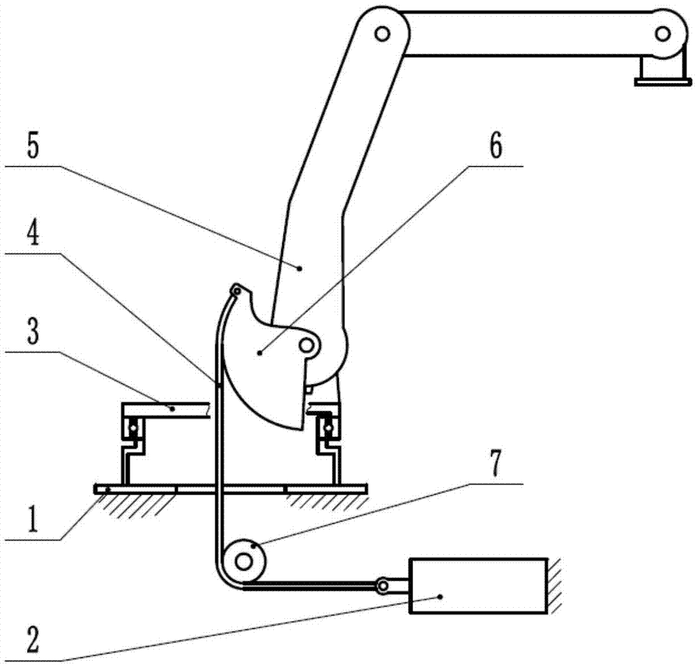
[0025] The other structure of this embodiment is the same as that of Embodiment 2, except that the transition block (6) is hinged on the robot arm (5), and there is a limit position on the robot arm, and the transition block can move within the limit stroke relative to the robot arm. Inward swing, the robot arm shrinks to a certain extent, when the assist force is no longer needed, the transition block is separated from the limit of the robot arm, and no assist is provided.


PUM


Abstract

The invention provides a power assisting device for a robot arm. The power assisting device comprises at least one assisting power source (such as a cylinder, a spring and a balance weight) arranged on a uniaxial rotary seat or a base of a robot, and a transmission tool connected with the output end of the power source, wherein the other end of the transmission tool is directly or indirectly connected with the robot arm. When the robot arm swings outwards under a load action to perform tilting action, the assisting power source provides reverse power assistance resisting the load gravity for the robot arm through the transmission tool, so that the power assisting requirement of the robot arm in different postures can be well met. A big enough assisting power can be provided, and the power assisting device can be well hidden and does not occupy the movement space of the robot.

Description

technical field [0001] The invention belongs to the robot driving technology, in particular to a power assist device for the movement of the first joint arm of an articulated robot. Background technique [0002] At present, robot power-assisted devices are widely used in heavy-duty palletizing and handling robots. Specific measures include adding counterweights, springs, gas springs, etc. However, due to volume and weight limitations, it is difficult for them to provide continuous and sufficient assisting force to meet the needs of different postures. It also hinders robot operation due to the space it takes up. To a certain extent, it limits the enlargement of heavy-duty robots. Contents of the invention [0003] In order to overcome the above-mentioned shortcomings, the object of the present invention is to provide a power assist device for the robot arm, especially the first joint arm, which can provide a large enough assist force, and can be well concealed and does n...

Claims


Application Information

Patent Timeline
Patent Type & Authority Applications(China)
IPC IPC(8): B25J19/00B25J18/04
CPCB25J19/00B25J18/04
Inventor 范红兵
Owner 范红兵
Why Eureka
Try Eureka