A hydraulic energy storage device with controllable input-output characteristics

A technology of hydraulic energy storage and output characteristics, applied in fluid pressure actuating devices, fluid pressure actuating system components, servo motors, etc., to solve problems such as uncontrollable motion, inability to switch energy storage capabilities, and inability to switch energy storage capabilities.

Active Publication Date: 2018-10-09
WUHAN UNIV OF TECH
View PDF5 Cites 0 Cited by
  • Summary
  • Abstract
  • Description
  • Claims
  • Application Information

AI Technical Summary

Problems solved by technology

[0003] In the actual work of the gas-type hydraulic accumulator, when the output (discharging), the oil in the accumulator will be released in an instant. Under the impact of high-pressure oil, the movement of hydraulic components such as the hydraulic valve spool is completely impossible. control, resulting in great vibration of the system; when input (liquid intake), the oil quickly enters the accumulator to compress the gas for energy storage, and when the energy storage reaches the upper limit and cannot be further stored, the only option is to replace the energy storage with a larger capacity The device cannot switch between different energy storage capacities according to different energy storage requirements
Therefore, the existing gas-type hydraulic accumulators have the problems of uncontrollable input-output characteristics and unswitchable energy storage capacity

Method used


Image

  • A hydraulic energy storage device with controllable input-output characteristics

Examples


Embodiment Construction

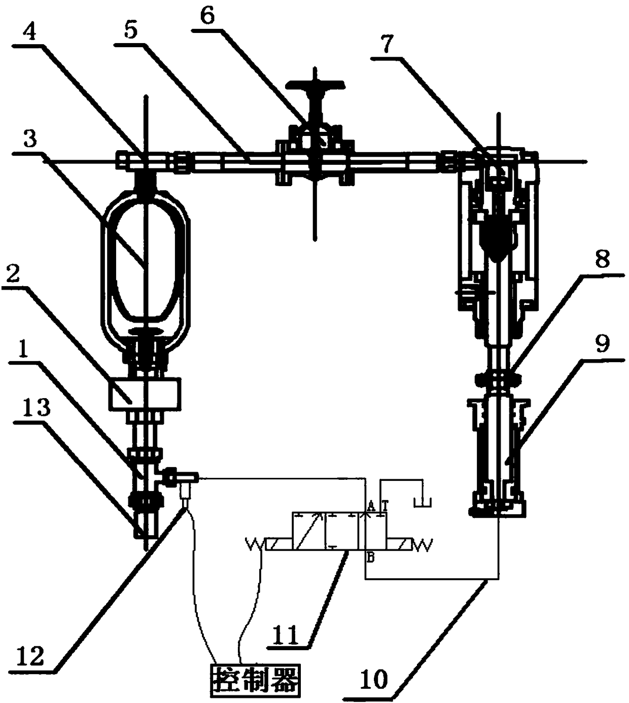
[0020] The present invention will be further described below in conjunction with the drawings and embodiments.

[0021] Such as figure 1 As shown, an input-output characteristic controllable hydraulic energy storage device includes a gas hydraulic accumulator 3 (the gas hydraulic accumulator 3 includes a pipeline vibration absorber, a gas-liquid direct contact type, a piston type, a diaphragm In this embodiment, the gas-type hydraulic accumulator 3 is a bladder-type accumulator) and a fuel tank. The liquid interface 2 of the gas-type hydraulic accumulator 3 is connected to the first port of the three-way pipe 1, The gas port 4 is connected to the gas source port of the single-acting pneumatic cylinder 7 through the gas pipe 5. The second port of the three-way pipe 1 is the liquid inlet and outlet 13 of the entire device. The gas pipe 5 is provided with a stop valve 6 and the piston of the single-acting pneumatic cylinder 7 The rod is connected to the piston rod of the single-act...


PUM


Abstract

The invention relates to an input-output characteristic controllable hydraulic energy storage device. The input-output characteristic controllable hydraulic energy storage device comprises an air type hydraulic energy accumulator and an oil tank. A liquid interface of the air type hydraulic energy accumulator communicates with a first port of a three-way pipe, an air interface communicates with an air source interface of a single acting pneumatic cylinder through an air pipe, and a second port of the three-way pipe is a liquid inlet-outlet of the whole device; a stop valve is arranged on the air pipe, a piston rod of the single acting pneumatic cylinder is connected to a piston rod of a single acting hydraulic cylinder, and a single acting hydraulic cylinder liquid source interface, a three-way pipe third port and the oil pipe communicate with an interface B, an interface A and an interface T of a three-position three-way electromagnetic valve correspondingly through oil pipes; three machine position states of the three-position three-way electromagnetic valve correspondingly comprise the modes that the interface B only communicates with the interface A, the interface B only communicates with the interface T, and the interface B, the interface A and the interface T do not communicate with one another; and a hydraulic sensor is arrange at the third port of the three-way pipe, and the three-position three-way electromagnetic valve and the hydraulic sensor are connected to a controller. The input-output characteristic controllable hydraulic energy storage device can control the input-output characteristics of the air type hydraulic energy accumulator and switch different energy storage capacities.

Description

Technical field [0001] The invention relates to a hydraulic energy storage device, in particular to a hydraulic energy storage device with controllable input-output characteristics. Background technique [0002] The most widely used hydraulic accumulator is the gas-type hydraulic accumulator. The gas-type hydraulic accumulator is based on Boyle's law and completes energy conversion by compressing gas. When using it, first charge the accumulator with gas at a predetermined pressure. , When the system pressure exceeds the internal pressure of the accumulator, the oil compresses the gas and converts the pressure in the oil into gas internal energy. When the system pressure is lower than the internal pressure of the accumulator, the oil in the accumulator is in the high-pressure gas Under the action of the flow to the external system, release energy. Gas hydraulic accumulators can also be subdivided into pipeline damper, gas-liquid direct contact type, piston type, diaphragm type, b...

Claims


Application Information

Patent Timeline
Patent Type & Authority Patents(China)
IPC IPC(8): F15B1/04F15B11/08F15B13/04F15B21/08
CPCF15B1/04F15B11/08F15B13/0401F15B21/08Y02E60/16
Inventor 刘艳雄华林徐志成
Owner WUHAN UNIV OF TECH
Why Eureka
Try Eureka