Test method for blade structure simulated member

A test method and blade structure technology, applied in machine/structural component testing, elastic testing, engine testing, etc., can solve problems such as frequent installation accidents, affecting the development and safe service of turbomachinery such as aero-engines

Inactive Publication Date: 2017-08-22
NORTHWESTERN POLYTECHNICAL UNIV
View PDF6 Cites 33 Cited by
  • Summary
  • Abstract
  • Description
  • Claims
  • Application Information

AI Technical Summary

Problems solved by technology

Although the simulated pieces of round rods with notches, flat plates, and thin-walled circular tubes reflect the complex / multiaxial stress state of the blade during service to a certain extent, due to the large difference from the actual stress state, based on the existing simulated piece test The blade design carried out often leads to frequent installation accidents, which seriously affects the development and safe service of aero-engine and other impeller machinery

Method used


Image

  • Test method for blade structure simulated member
  • Test method for blade structure simulated member
  • Test method for blade structure simulated member

Examples


Embodiment Construction

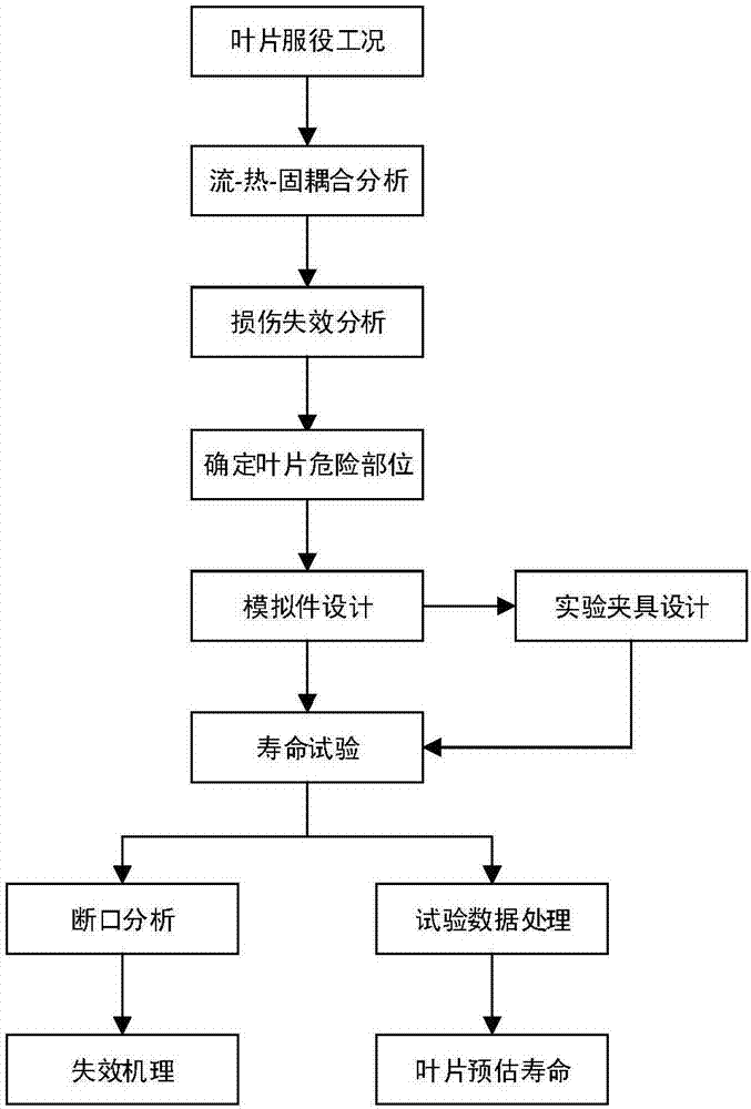
[0024] Technical scheme of the present invention comprises the following steps:

[0025] Step 1: Analyze the temperature field and stress field of the blade: through the fluid-thermal-solid coupling analysis, the temperature field and stress field of the blade in service state are obtained;

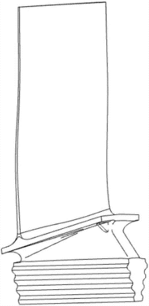
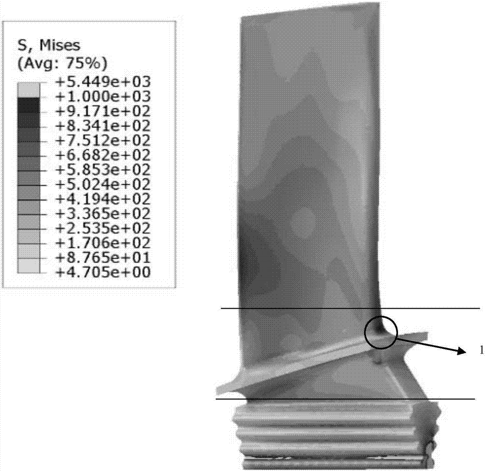
[0026] Step 2: Combining the numerical calculation results of step 1 with the actual fault to determine the dangerous position of the blade: for the service condition of the blade, analyze the damage and failure of the blade based on the life prediction model, and refer to the crack position and fault condition of the blade in use of the engine to determine the blade is easy Hazardous parts where damage occurs1;

[0027] Step 3: Design of blade simulation parts: Design the test section 2, transition sections 3, 4 of the simulation piece and the support sections 5, 6, 7, 8 connected to the testing machine respectively, to ensure the strain, temperature conditions and actual operating condi...


PUM


Abstract

The invention relates to a test method for a blade structure simulated member. The design of a blade body simulated member is carried out based on the principle that damaged parts are in the same shape and stress and stress distribution are identical or similar, and the stress state of a dangerous part during the blade operation process can be effectively reflected. By adopting the test method, load and temperature at a dangerous section of the blade are applied to the simulated test piece for conducting a fatigue, creep and interaction life test, such that the service life of the blade can be determined precisely, and the damage failure mechanism of the blade can be revealed.

Description

technical field [0001] The invention relates to a test method of a blade structure simulation part, which can be used for testing the fatigue life and enduring life of blade structures of aero-engines, gas turbines, steam turbines and the like. Background technique [0002] Aeroengines, ground gas turbines, steam turbines and other impeller machinery need to go through the process of starting, running and stopping. Under the joint action of centrifugal load, thermal load and aerodynamic load, the structure is prone to high cycle fatigue damage, low cycle fatigue damage and creep damage and interaction damage. According to the statistics of US military aircraft, more than 90% of aero-engine accidents are caused by component strength and fatigue damage. As the core components of turbomachinery, compressor blades and turbine blades are one of the structures with the worst working environment in turbomachinery, and are more prone to damage and damage. Therefore, accurate predic...

Claims


Application Information

Patent Timeline
Patent Type & Authority Applications(China)
IPC IPC(8): G01M15/00G01M5/00
CPCG01M5/0016G01M5/0075G01M15/00
Inventor 李磊康家磊孙守义唐仲豪陈太宇万欢岳珠峰高行山
Owner NORTHWESTERN POLYTECHNICAL UNIV
Why Eureka
Try Eureka