Structured light projection device and depth camera

A technology of structured light projection and projection device, which is applied in optics, photography, instruments, etc., and can solve problems such as poor depth images, high cost, and large-area voids

Active Publication Date: 2019-07-12
SHENZHEN ORBBEC CO LTD
View PDF5 Cites 0 Cited by
  • Summary
  • Abstract
  • Description
  • Claims
  • Application Information

AI Technical Summary

Problems solved by technology

[0003] One of the problems faced by the current structured light depth camera in use is that when the measurement areas of multiple depth cameras overlap, the obtained depth image will be poor, and even large areas of holes will appear.
Even so, realizing the above-mentioned anti-jamming methods all need to spend relatively large cost

Method used


Image

  • Structured light projection device and depth camera
  • Structured light projection device and depth camera
  • Structured light projection device and depth camera

Examples


Embodiment 1

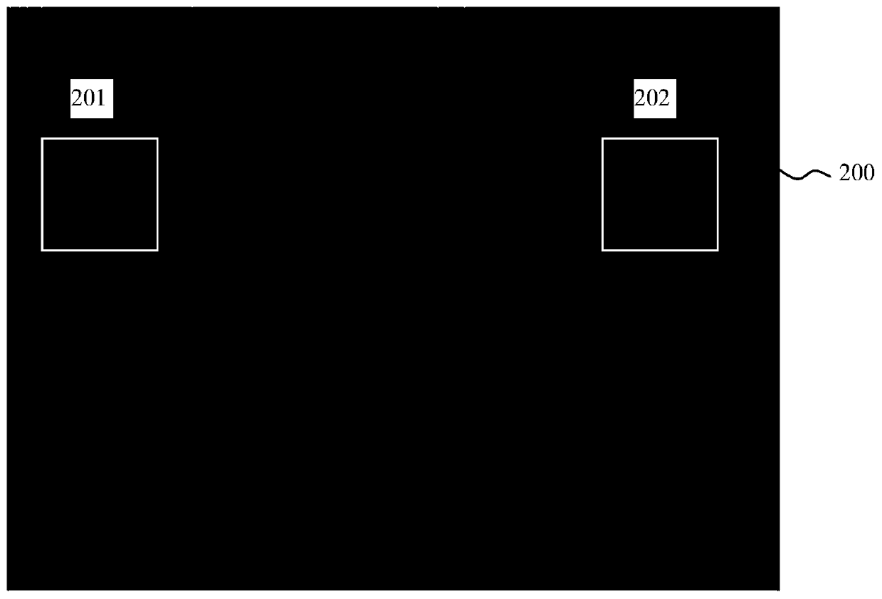
[0037] This embodiment provides a structured light projection device, in which the structured light pattern emitted into the target space is a laser infrared speckle pattern. Such as Figure 2a As shown, the structured light pattern 200 is a kind of speckle particle pattern. The difference from the prior art is that the distribution density of the particles in the pattern 200 changes along the lateral direction, specifically refers to the increasing particle distribution density in the lateral dimension. smaller. As shown in FIG. 2 , when a sub-region of the pattern is selected, it can be clearly seen that the number of particles in the sub-region 201 on the left is greater than that in the sub-region 202 on the right. In other embodiments, the distribution density of the particles increases in the transverse dimension.

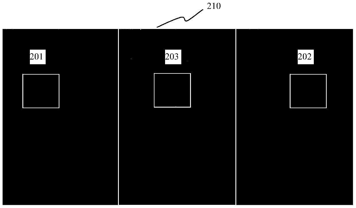
[0038] Figure 2b The pattern 210 shown is when two depth cameras are placed side by side and the measurement volumes partially overlap. The pattern 210 ...

Embodiment 2

[0042] This embodiment provides a structured light projection device, in which the structured light pattern emitted into the target space is a laser infrared fringe pattern. Such as Figure 3a As shown, the structured light pattern 300 is composed of a plurality of rectangular sub-patterns, and the left side of the pattern is a vertical rectangle, and the right side is a horizontal rectangle. Therefore, the structured light pattern 300 also changes in the lateral direction, but the shape changes instead of the density change. It can be extended that, in other embodiments, the right side can also be in other styles such as a circle, that is, the pattern changes along the horizontal direction.

[0043] Figure 3b What is shown is the situation where the structured light pattern 300 overlaps left and right. It can be seen that in the overlapping area, due to the different shapes of the rectangles, even if the rectangles are coupled together, the vertical and horizontal aspects ...

Embodiment 3

[0046] The structured light patterns in Embodiments 1 and 2 change along a certain direction, and the structured light patterns of multiple depth cameras can only overlap along this direction when overlapping, otherwise it is difficult to achieve the anti-interference effect. For example, when the density of the structured light pattern changes along the left and right, and the corresponding depth camera partially overlaps up and down, the depth image acquired by the depth camera still cannot have a good effect.

[0047] It is necessary to design a structured light pattern that can overlap in any direction and achieve anti-interference.

[0048] Figure 4a The structured light pattern shown can be regarded as the center of the pattern as the origin, and changes with the polar coordinates as the radius increases, and the specific change is the shape of the sub-pattern (the change in the radius). The sub-pattern shown in the figure is in the shape of a whole ring, or it may be ...


PUM


Abstract

The present invention provides a structured light projection device, which includes a light source and a pattern generator. The light beam emitted by the light source forms a structured light pattern through the pattern generator and is emitted outward. The structured light pattern changes in at least one dimension, so that in the The structured light patterns can be resolved when a plurality of the structured light patterns overlap at least partially in the at least one dimension. Compared with the depth camera disclosed in the prior art, it solves the problem of interference from the source, changes the structured light pattern emitted by the projection module, and makes the structured light pattern have the characteristic of changing along a certain dimension, so that when multiple When the measurement space of the depth camera partially overlaps, the structured light pattern in the overlapping area can still be clearly distinguished, so that the acquisition of the depth image will not be affected by the pattern overlap, so as to achieve the purpose of anti-interference.

Description

technical field [0001] The invention relates to the technical field of optical projection and measurement, in particular to an anti-interference structured light projection device and a depth camera. Background technique [0002] Depth cameras based on structured light are currently widely used in somatosensory games, robotics and UAV vision systems due to their advantages of high precision and fast acquisition speed. The depth camera projects a fixed structured light pattern to the target space through the projection module, and then the acquisition camera in the depth camera collects the structured light image of the target space, and calculates the depth image of the target space according to the decoding of the structured light image . [0003] One of the problems faced by the current structured light depth camera in use is that when the measurement areas of multiple depth cameras overlap, the acquired depth image will be poor, and even large areas of holes will appear....

Claims


Application Information

Patent Timeline
Patent Type & Authority Patents(China)
IPC IPC(8): G03B15/02G03B30/00
CPCG03B15/02
Inventor 黄源浩肖振中刘龙许星
Owner SHENZHEN ORBBEC CO LTD
Why Eureka
Try Eureka