Perforation shock absorber device

A shock absorber and through-hole technology, which is applied in the direction of mining fluid, wellbore/well components, earthwork drilling, etc., can solve the problems of unsatisfactory shock absorption effect, unsatisfactory shock absorption effect, and non-reusable use. To achieve the effect of simple structure, good shock absorption effect and smooth operation

Active Publication Date: 2018-06-29
CHINA UNIV OF PETROLEUM (BEIJING)
View PDF6 Cites 0 Cited by
  • Summary
  • Abstract
  • Description
  • Claims
  • Application Information

AI Technical Summary

Problems solved by technology

[0003] In recent years, the structure of the shock absorber has been continuously improved. It has gradually developed from the previous single spring or rubber tube damping method to the current combined effect of the rubber tube, hydraulic pressure, spring, etc., and has made great progress. There are some problems, such as: the stability of the rubber is poor, the rubber deformation of the rubber shock absorber is serious after one use, and even the rubber will be squeezed out from the breathing hole, which seriously affects the effect of the next use, and cannot even be reused; for hydraulic shock absorbers When the perforation vibrates, the liquid in the liquid cavity is compressed, and the liquid discharge speed is controlled by the number of liquid discharge holes, so as to achieve the purpose of shock absorption. However, if there is no liquid cushion in the well test process, the shock absorption effect It is very unsatisfactory; at the same time, most of the current shock absorbers can only absorb shocks in one direction, so the effect of shock absorption is generally not ideal

Method used


Image

  • Perforation shock absorber device
  • Perforation shock absorber device
  • Perforation shock absorber device

Examples


Embodiment Construction

[0053] In order to have a clearer understanding of the technical features, purposes and effects of the present invention, the specific implementation manners of the present invention will now be described with reference to the accompanying drawings.

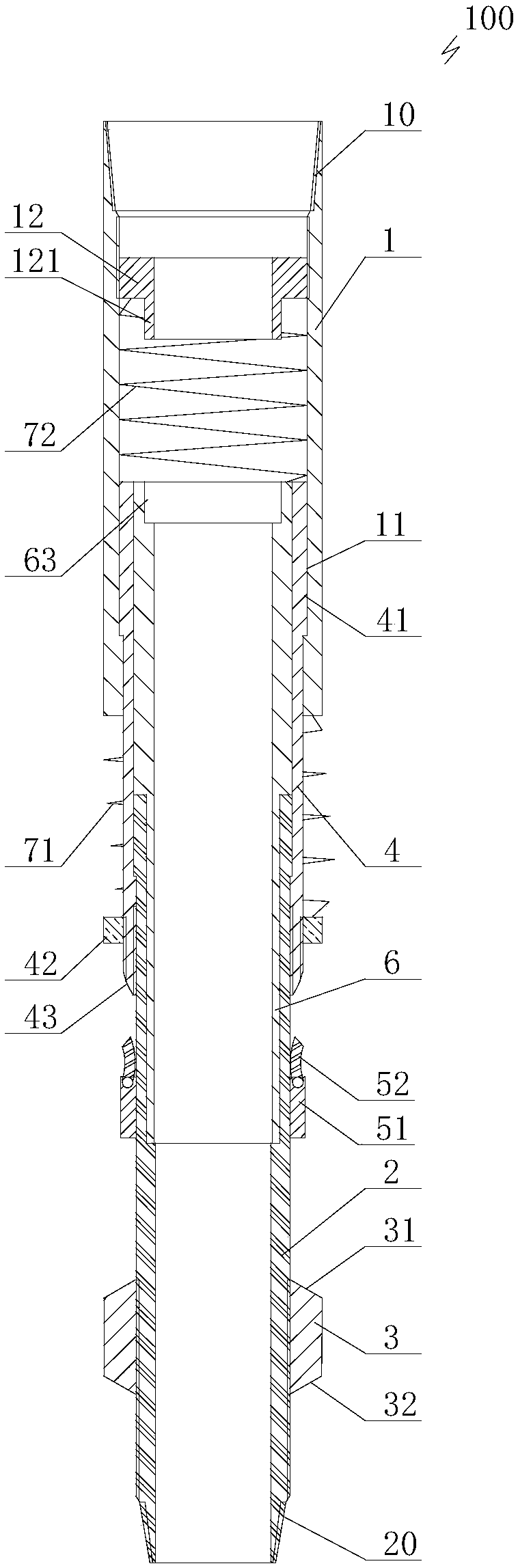
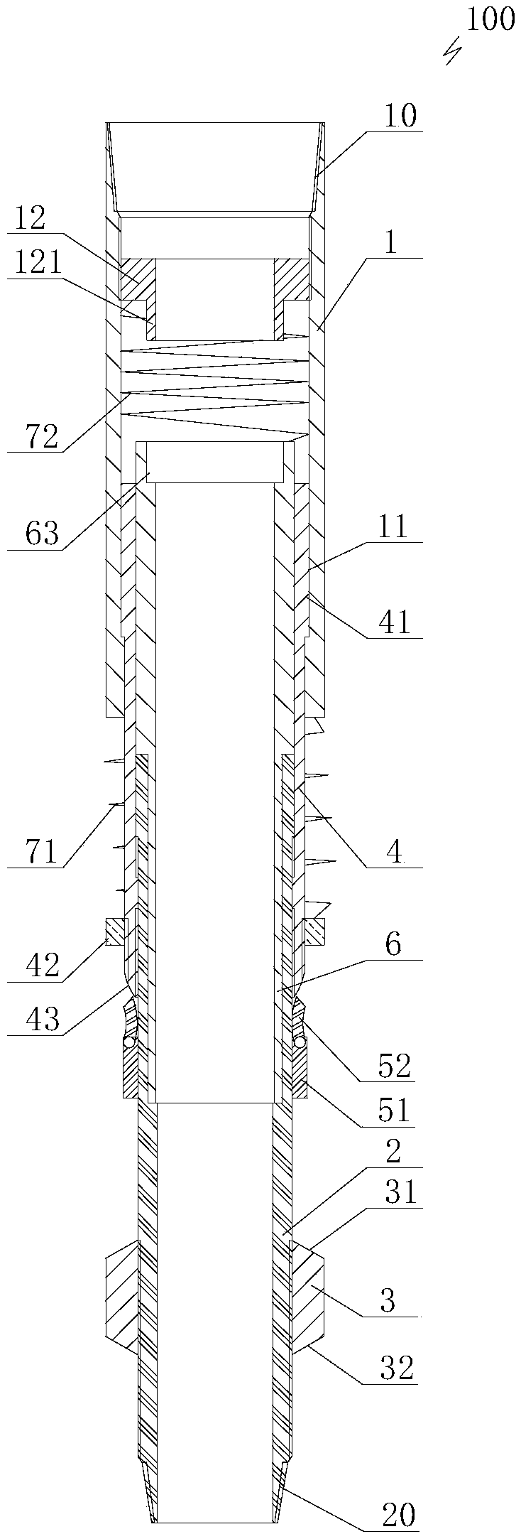
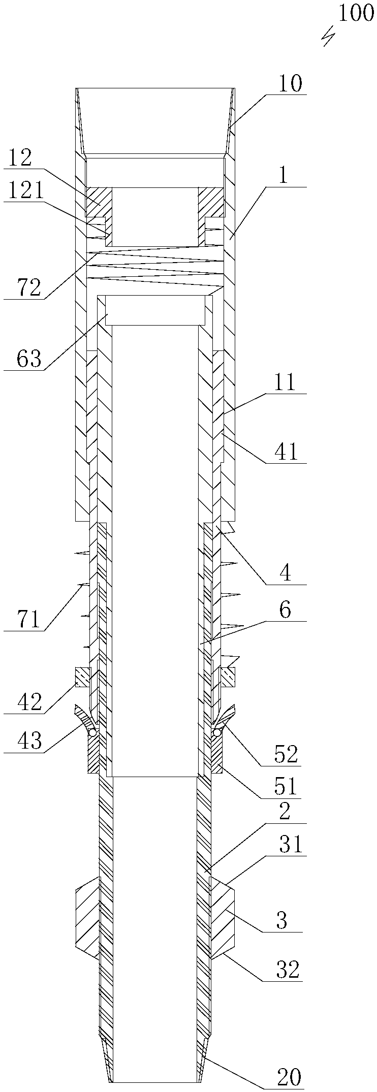
[0054] like Figure 1 to Figure 10 As shown, the present invention provides a perforation shock absorber device 100, including the top energy and the upper pipe string 91 (the perforation pipe string is separated into two parts, the upper pipe string 91 and the lower pipe string 92 by the perforation shock absorber device) The connected upper cylinder 1 and the lower cylinder 2 whose bottom can be connected with the lower pipe string 92. In this embodiment, the top of the inner wall of the upper cylinder 1 is provided with an internal taper threaded part 10 for connecting the upper pipe string 91. The bottom of the outer wall of the cylinder 2 is provided with an external taper thread part 20 for connecting the lower pipe string ...


PUM


Abstract

The invention discloses a perforation damper device. The perforation damper device comprises an upper drum and a lower drum. The lower part of the outer wall of the lower drum is sleeved with a friction drum. A transition drum is arranged on the outer wall of the upper part of the lower drum in a sleeving mode, and the transition drum is fixed on the lower drum in the axial direction and can rotationally move along the lower drum. The lower part of the upper drum can drive the transition drum to be rotationally and slidably arranged on the outer wall of the transition drum. The upper drum can be clamped on the transition drum upward in the axial direction, and can slide downward to form an axial damping gap therebetween with the transition drum. The portion, on the outer wall of the lower portion of the transition drum, of the lower drum is sleeved with a bending clamp fixing sleeve which is fixed through radial shear pins, and can slide along the lower drum. A plurality of bending clamps are hinged to the top of the bending clamp fixing sleeve at intervals in the circumference direction, and the bending clamps can abut against the bottom of the transition drum to open radially and contract radially. According to the perforation damper device, the vibration energy of a pipe column can be absorbed during perforation, the construction safety is improved, and the fact that the perforation and the test are conducted successfully is ensured.

Description

technical field [0001] The invention relates to the technical field of petroleum perforation, in particular to a perforation shock absorber device. Background technique [0002] Perforation is an extremely important technology in petroleum exploration and development system engineering, and perforation completion is the most widely used well completion method at home and abroad. Perforation technology refers to transporting special instruments and equipment for perforation to the predetermined position in the well, aiming at the target layer to detonate the perforator, and after the shaped energy perforating charge is detonated by the detonation index, the detonation wave moves forward at 7000-8000 m / s Propagate, generate high-pressure shock waves, so as to penetrate the casing and cement sheath into the formation, form a tunnel, and constitute a technology that connects the target layer to the inside of the casing. At present, the perforation technology at home and abroad ...

Claims


Application Information

Patent Timeline
Patent Type & Authority Patents(China)
IPC IPC(8): E21B43/119
CPCE21B43/119
Inventor 李军黄涛张辉
Owner CHINA UNIV OF PETROLEUM (BEIJING)
Why Eureka
Try Eureka