Fan Frame of an Axial-Flow Fan

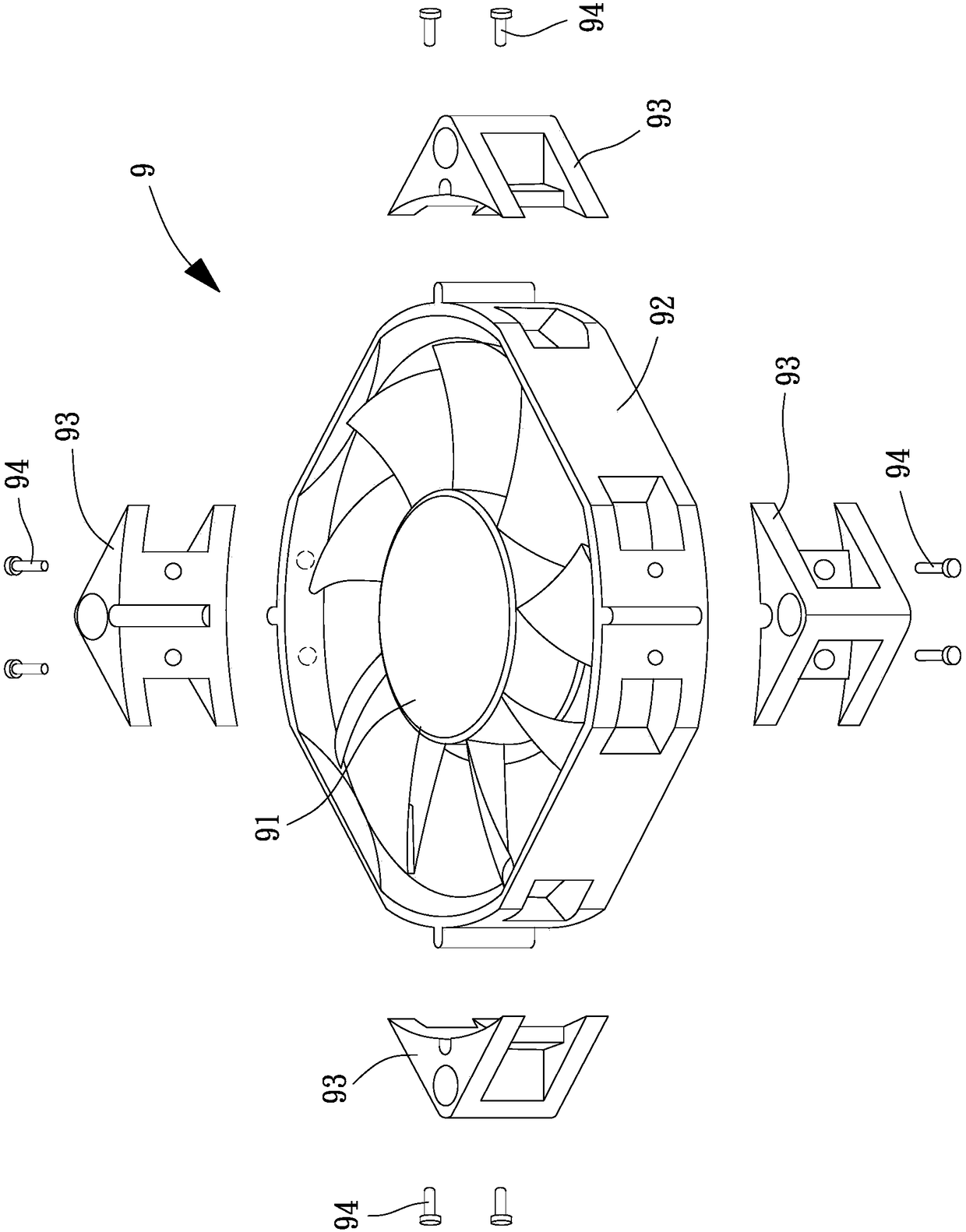
A technology of axial flow and fan, applied in axial flow pumps, components of pumping devices for elastic fluids, non-variable pumps, etc., can solve the numerous assembly steps and the overall structural complexity of axial flow fans 9 High, axial flow fan 9 assembly convenience and poor efficiency, to achieve the effect of simplifying the structure of the fan frame

Inactive Publication Date: 2018-05-29
SUNONWEALTH ELECTRIC MACHINE IND
View PDF7 Cites 0 Cited by
  • Summary
  • Abstract
  • Description
  • Claims
  • Application Information

AI Technical Summary

Problems solved by technology

[0003] However, the existing axial flow fan 9 must additionally combine the anti-vibration assembly 93 outside the fan frame 92, because the fan frame 92 and the anti-vibration assembly 93 are components manufactured separately, and the respective components must be provided with a connection for mutual assembly. structure, so that the overall structural complexity of the existing axial flow fan 9 is high
[0004] At the same time, the axial flow fan 9 needs to pre-assemble the anti-vibration component 93 to a predetermined position on the fan frame 92, and further lock the anti-vibration component 93 to the fan frame 92 with a plurality of fixing pieces 94. Complete the assembly, so there are many assembly steps, which make the assembly convenience and efficiency of the existing axial flow fan 9 poor

Method used


Image

  • Fan Frame of an Axial-Flow Fan
  • Fan Frame of an Axial-Flow Fan
  • Fan Frame of an Axial-Flow Fan

Examples


Embodiment Construction

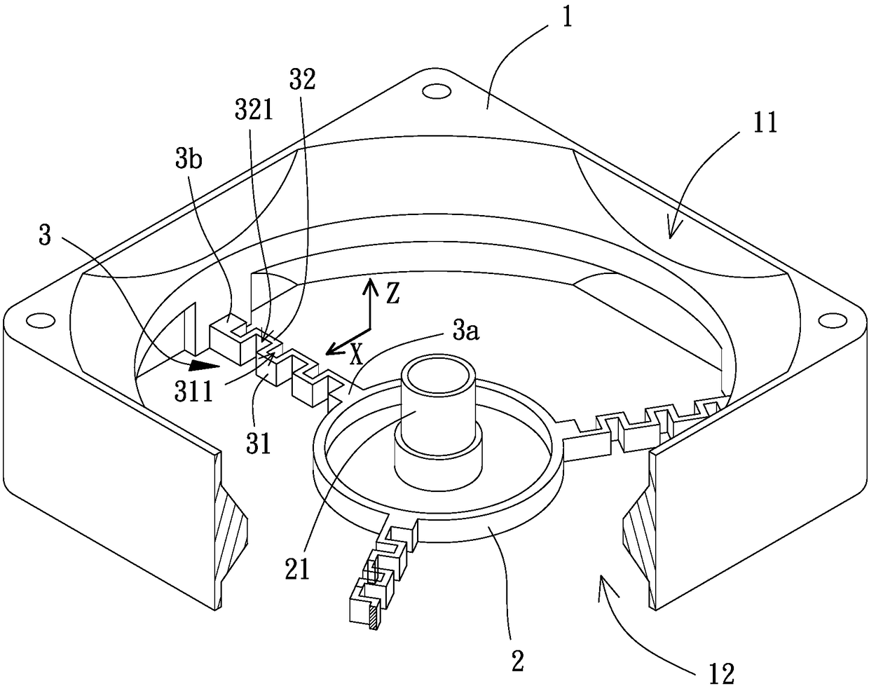
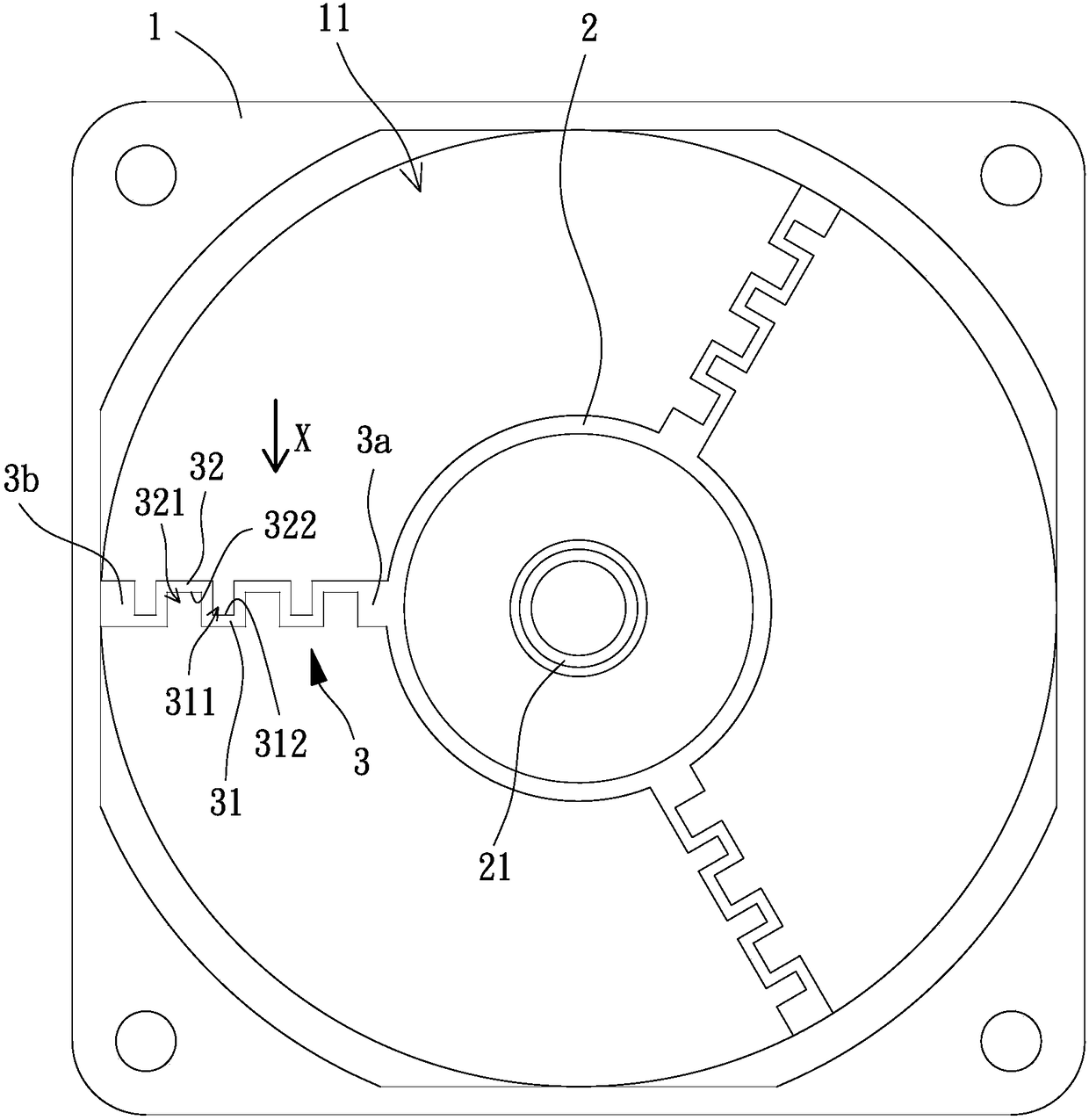
[0072] In order to make the above-mentioned and other objects, features and advantages of the present invention more comprehensible, the following is based on the preferred embodiments of the present invention and is described in detail as follows in conjunction with the accompanying drawings:

[0073] Please refer to figure 2 and 3 As shown, the fan frame of the axial flow fan according to the first embodiment of the present invention includes a casing 1, a base 2 and a plurality of connecting pieces 3, and each connecting piece 3 connects the casing 1 and the base 2 respectively. . The casing 1 is respectively provided with a vent 11 and 12 on both sides of an axial direction Z, and the two vents 11 and 12 can be used as an air inlet and an air outlet of an axial flow fan.

[0074] The base 2 has a shaft connection portion 21 extending along the axial direction Z, and the shaft connection portion 21 can be provided for the shaft of the axial flow fan. In detail, a bearin...


PUM


Abstract

A fan frame of an axial-flow fan is provided to reduce the vibration generated during the rotation of the impeller that is transmitted to the outside of the axial-flow fan via the fan frame. The fan frame includes a housing, a base and a plurality of connection members. The base includes a shaft-coupling portion. Each of the plurality of connection members includes two ends respectively connectedto the housing and the base. Each of the plurality of connection members is defined with an extension line passing through the two ends of the connection member. Each of the plurality of connection members includes at least one first bending portion and at least one second bending portion. The at least one first bending portion extends around a first notch, and the at least one second bending portion extends around a second notch. The extension line extends through the first and second notches.

Description

technical field [0001] The invention relates to a fan frame of an axial flow fan, in particular to a fan frame of an axial flow fan with a damping function. Background technique [0002] Please refer to figure 1 , which is an existing axial flow fan 9, which has a fan wheel 91, a fan frame 92 and a plurality of anti-vibration components 93, and the fan wheel 91 is rotatably arranged in the fan frame 92. Each anti-shock assembly 93 is combined and positioned on the side wall of the fan frame 92, and each anti-shock assembly 93 can be made of a material with good elasticity, which can provide a buffer function to prevent the vibration generated by the fan wheel 91 from passing through the fan wheel 91. The frame 92 is transmitted to the outside of the axial flow fan 9, so as to avoid generating noise or affecting system stability. An embodiment similar to the axial flow fan 9 has been disclosed in the patent case "Fan and Fan Frame" published in Taiwan, China, No. M445644. ...

Claims


Application Information

Patent Timeline
Patent Type & Authority Applications(China)
IPC IPC(8): F04D29/52F04D29/66
CPCF04D29/522F04D29/668F04D19/002F04D25/0613
Inventor 洪银树梁胜杰麦志豪
Owner SUNONWEALTH ELECTRIC MACHINE IND
Why Eureka
Try Eureka