
Device for laying a conductive wire for welding

A technology of conductive wires and wires, which is applied in the field of devices for laying conductive wires for welding, and can solve the problems that the small radius or curvature of the welding wire cannot be well applied, and the management and welding cannot be well applied.

Active Publication Date: 2017-08-29
RENAULT SA
View PDF2 Cites 0 Cited by
  • Summary
  • Abstract
  • Description
  • Claims
  • Application Information

AI Technical Summary

Problems solved by technology

However, this type of welding is not well suited to complex three-dimensional surfaces, or to small radii or curvatures of the weld line, and moreover, preparation systems using liquid materials are expensive and difficult to adapt to the length of the weld. manage
What's more, this material addition creates extra thickness between parts after welding and does so in a non-constant manner

Method used


Image

  • Device for laying a conductive wire for welding
  • Device for laying a conductive wire for welding
  • Device for laying a conductive wire for welding

Examples


Embodiment Construction

[0023] In the description section below, it is considered that the top corresponds to figure 1 The top and bottom correspond to figure 1 bottom of.

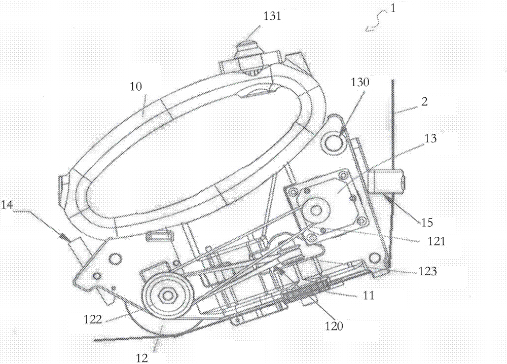
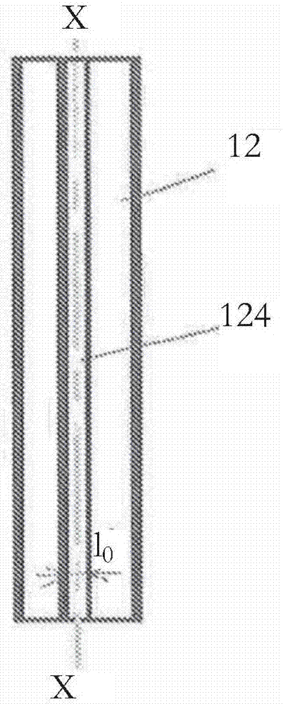
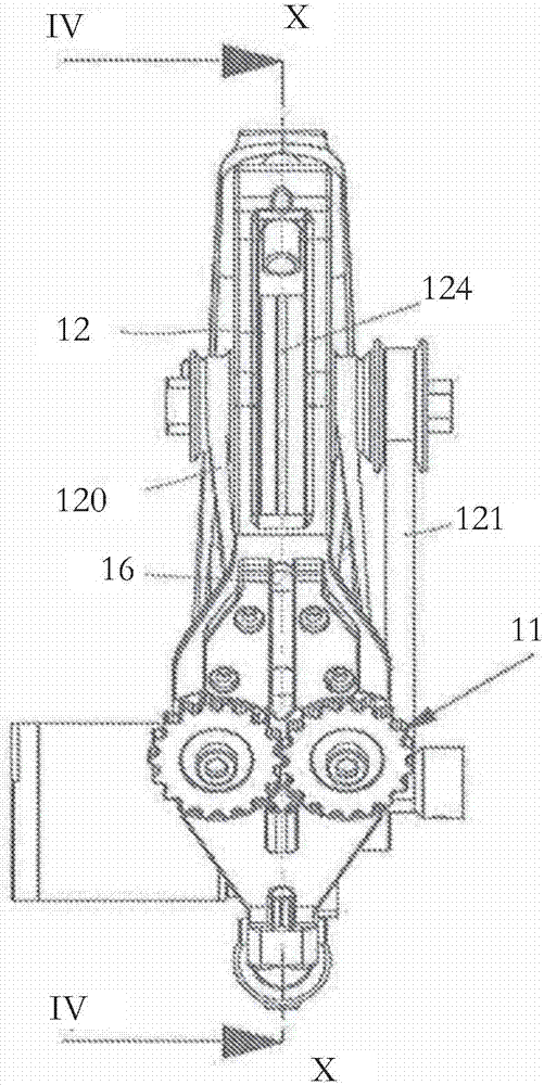
[0024] Such as figure 1 The device according to the invention, visible in FIG. 2 , comprises a spray gun 1 and a wire 2 provided by a wheel (not depicted) and arriving via a support 15 . The spray gun 1 has a handle 10 by means of which an operator can operate the spray gun 1 . The device also comprises two toothed wheels 11 and a laying wheel 12 . The laying wheel 12 is driven by a belt 121 connected to an electric drive motor 13 and the toothed wheel 11 is driven by a belt 120 connected to the laying wheel 12 . Thus, the toothed wheel 11 and the laying wheel 12 are driven together in a coordinated manner. The belts 120, 121 are connected to the wheels by toothed pulleys 122, 123 in a known manner. The drive belt 121 between the motor shaft 13 and the shaft of the laying wheel 12 is a toothed belt. There are two toothed d...


PUM


Abstract

The invention relates to a device for laying a conductive wire (2) on a thermoplastic surface, characterised in that it comprises a system for heating said conductive wire (2). The heating of the conductive wire (2) allows the wire to be placed on the surface of one of the parts to be welded, and the wire is heated again in order to perform the welding of the two parts.

Description

technical field [0001] The present invention relates to a device that allows welding between two thermoplastic components such as tailgates, spoilers, side doors, etc. Background technique [0002] Until now, this type of bonding has been achieved by laser welding, bonding or by adding liquid or solid materials in the form of "patches". These patches are made of the material of the parts to be welded into which conductive particles of the material have been embedded. These conductive particles are heated inductively, causing the material to melt, thus welding the parts together. However, this type of welding is not well suited to complex three-dimensional surfaces, or to small radii or curvatures of the weld line, and moreover, preparation systems using liquid materials are expensive and difficult to adapt to the length of the weld. to manage. What's more, this material addition creates extra thickness between parts after welding and does so in a non-constant manner. Co...

Claims


Application Information

Patent Timeline
IPC IPC(8): B29C65/36B29C65/44
CPCB29C65/362B29C65/3676B29C65/44B29C66/1122B29C66/221B29C66/301B29C66/349B29C66/69B29C66/7392B29C66/73921B29C66/742B29C66/8181B29C66/8362B29C66/861B29C66/7422B29C66/74281B29C66/74283B29C66/81431B29C66/8161B29C66/919B29C66/939B29C70/82
Inventor A·托内尔A·菲利普M·米哈鲁塔
Owner RENAULT SA
Learn More