N nail buckling device

A technology of nailing buttons and working boards, which is applied in the field of mechanical equipment, can solve the problems of slow manual packaging and achieve the effect of automatic fastening

Inactive Publication Date: 2017-09-05
GUANGZHOU MEITE AUTOMOBILE TECH CO LTD
View PDF0 Cites 0 Cited by
  • Summary
  • Abstract
  • Description
  • Claims
  • Application Information

AI Technical Summary

Problems solved by technology

[0003] The purpose of the present invention is to overcome the slow speed of manual packaging today, improve the accuracy of packaging, and reduce the complicated process

Method used


Image

  • N nail buckling device
  • N nail buckling device
  • N nail buckling device

Examples


Embodiment Construction

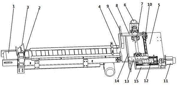
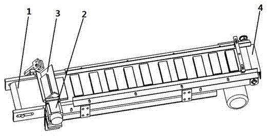
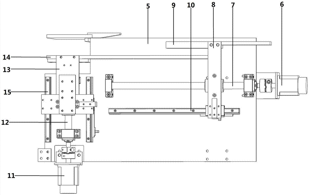
[0015] An N nail fastening device, comprising a conveyor belt 1, a turning mechanism installed at the front end of the conveyor belt, a connecting plate 4 installed at the tail of the conveyor belt 1, a working plate 5 connected to the connecting plate 4, and a control mechanism installed on the working plate 5 One, connect the pushing plate 9 of the first control mechanism, the second control mechanism installed on the working plate 5, and connect the baffle plate 14 of the second control mechanism.

[0016] There is a height difference between the working board 5 and the connecting board 4, and the working board 5 is 3-8 cm lower than the connecting board 4.

[0017] The turning mechanism includes a turning plate 3 and a motor one 2, and the turning plate 3 is connected with the motor one 2 through transmission.

[0018] Described control mechanism one comprises motor two 6, screw mandrel one 7, connection block one 8, slide rail one 10, and described slide rail one 10 is in...


PUM


Abstract

The invention belongs to the technical field of mechanical equipment, and specifically provides an N-nail fastening device, which includes a conveyor belt, and is characterized in that it also includes a turning mechanism installed at the front end of the conveyor belt, a connecting plate installed at the tail of the conveyor belt, and a connecting plate connected to the connecting plate. Working plate, the control mechanism one installed on the working plate, the push plate connected with the control mechanism one, the control mechanism two installed on the working plate, the baffle plate connected with the control mechanism two. It solves the problem of slow packaging speed and low efficiency of N nails, and has the effect of realizing automatic fastening of N nails, which can provide great convenience for subsequent packaging.

Description

technical field [0001] The invention belongs to the technical field of mechanical equipment, and in particular relates to an N-nail fastening device. Background technique [0002] The packaging speed of the N nails produced in the domestic market is slow and the efficiency is low, mainly because it is manually buckled, arranged and stacked for packaging. Without solving this problem, some inventors have developed technologies that can realize automatic packaging of N-nails, for example, a device for realizing N-nail interlocking with Chinese patent No. 2015206767375, which discloses a device for realizing N-nail interlocking, including Workbench, support, stacking device 1, jacking mechanism, stocking device 2, and pushing device, the stacking device 1, jacking mechanism, stacking device 2, and pushing device are all installed on the workbench; The first stacking device and the ejecting mechanism are on the same horizontal line, and the second stacking device and the pushin...

Claims


Application Information

Patent Timeline
IPC IPC(8): B65B35/30B65B35/56
CPCB65B35/30B65B35/56
Inventor 唐楚源王诗篇
Owner GUANGZHOU MEITE AUTOMOBILE TECH CO LTD
Why Eureka
Try Eureka