Push eject lock and washing machine
A technology of snapping and locking, applied in the field of washing machines, can solve the problems of different user's hand and body feeling and low comfort in use.
- Summary
- Abstract
- Description
- Claims
- Application Information
AI Technical Summary
Problems solved by technology
Method used
Image
Examples
Embodiment 1
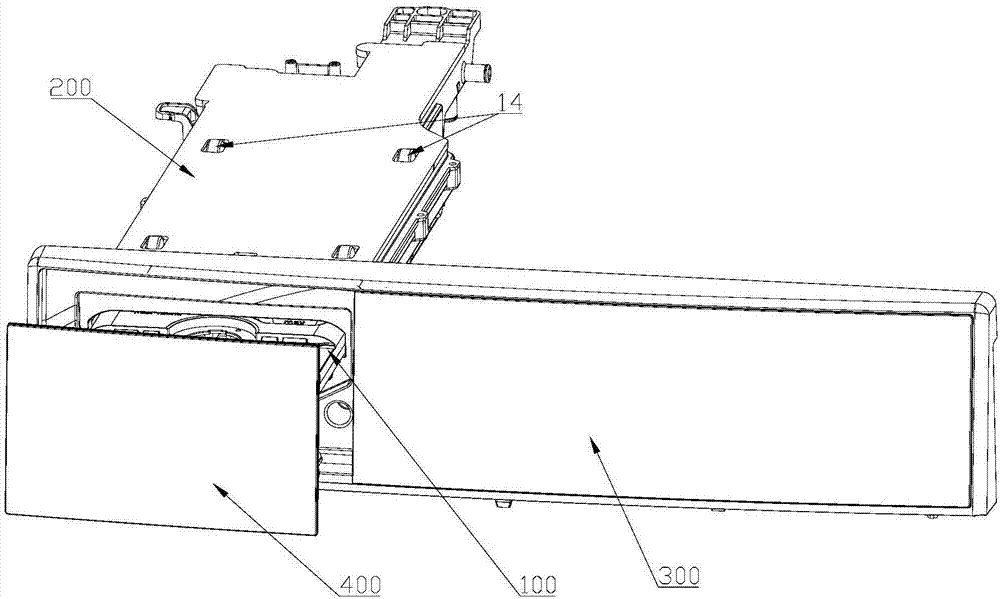
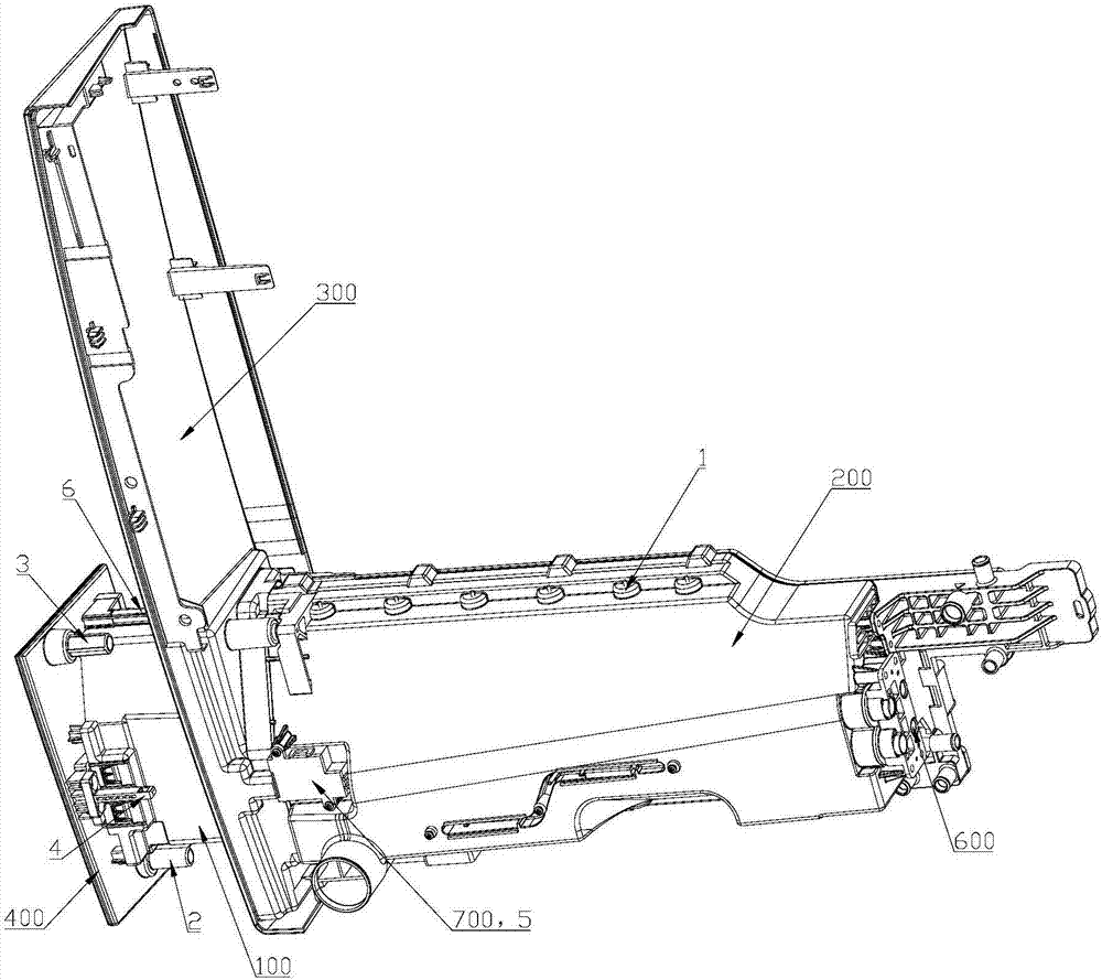
[0047] Such as Figure 1 to Figure 12 As shown, in this embodiment, a push-to-play detergent box is introduced, including a water box 200 installed on the washing machine casing 300, and a pull-out and push-in detergent box 100 is installed in the water box 200; A slide rail structure is provided between the water box 200 and the detergent box 100, and the slide rail structure includes a plurality of pulleys 1 in contact with the detergent box 100, so as to reduce the friction during the pulling and pushing process of the detergent box 100.
[0048] By installing the detergent box and the water box through the pulley and slide rail structure, the friction at the displacement contact between the detergent box and the water box is changed from sliding friction to rolling friction, which greatly reduces the friction in the process of pushing and pulling the detergent box force.
[0049] In this embodiment, the left and right sides of the detergent box 100 are respectively provid...
Embodiment 2
[0061] Such as Figure 1 to Figure 12 As shown, in this embodiment, a push-to-play detergent box is introduced, which includes a water box 200 installed on the shell of the washing machine, and a pull-out and push-in detergent box 100 is installed in the water box 200; The top of the detergent box 100 is provided with a fastened upper cover 500, and the top wall of the water box 200 is equipped with a plurality of vertically installed limit pulleys 14 protruding from the lower surface of the top wall to reduce the amount of detergent. The process of pulling out and pushing in the box 100 is frictional.
[0062] A plurality of limit pulleys are arranged between the upper cover of the detergent box and the top wall of the water box to avoid direct contact between the upper cover of the detergent box and the top wall of the water box, so that the limit pulleys are aligned during the pushing and pulling of the detergent box. The upper cover of the detergent box provides sliding f...
Embodiment 3
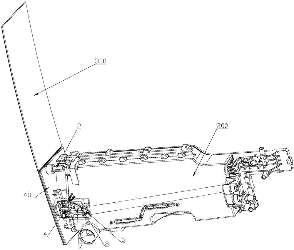
[0074] Such as Figure 1 to Figure 3 and Figure 13 to Figure 18 As shown, this embodiment introduces a push-to-ball lock applied to the push-to-pop detergent box of the present invention, which includes a lock tongue 4 and a push-to-ball lock body 5, and the lock tongue 4 can be movably inserted into the push-to-ball lock body 5 Inside, the push ball lock body 5 is equipped with a cam 7, and the cam 7 is provided with a groove cooperating with the lock hook 21 at the end of the dead bolt 4; One end of the snap reed 8 is fixed to the push spring lock body 5 , and the other end is provided with a snap 24 that matches the snap slide on the cam 7 to lock or unlock the rotation of the cam 7 .
[0075] In this embodiment, the outer circumference of the cam 7 is respectively provided with radially protruding first protrusions 19 and second protrusions 20, and the gap between the first protrusions 19 and the second protrusions 20 constitutes a 4. The locking hook 21 at the end corr...
PUM
 Abstract
Description
Claims
Application Information
 - R&D
- Intellectual Property
- Life Sciences
- Materials
- Tech Scout
- Unparalleled Data Quality
- Higher Quality Content
- 60% Fewer Hallucinations
Browse by: Latest US Patents, China's latest patents, Technical Efficacy Thesaurus, Application Domain, Technology Topic, Popular Technical Reports.
© 2025 PatSnap. All rights reserved.Legal|Privacy policy|Modern Slavery Act Transparency Statement|Sitemap|About US| Contact US: help@patsnap.com


