A reducer installation structure

A technology of installation structure and reducer, which is applied in the direction of printing device, printing, etc., can solve the problems of broken reducer, high rigidity of roller shaft, etc., and achieve the effect of reducing the requirement of the same cylinder, improving efficiency and preventing connection failure

Active Publication Date: 2019-02-26
驱动数码电子(广东)有限公司
View PDF6 Cites 0 Cited by
  • Summary
  • Abstract
  • Description
  • Claims
  • Application Information

AI Technical Summary

Problems solved by technology

However, the rigidity of the roller shaft is relatively high, especially for the roller shaft of a large conveyor belt, the requirement for the same cylinder between the output shaft of the reducer and the roller shaft is higher, otherwise the reducer will be damaged

Method used


Image

  • A reducer installation structure
  • A reducer installation structure
  • A reducer installation structure

Examples


Embodiment 1

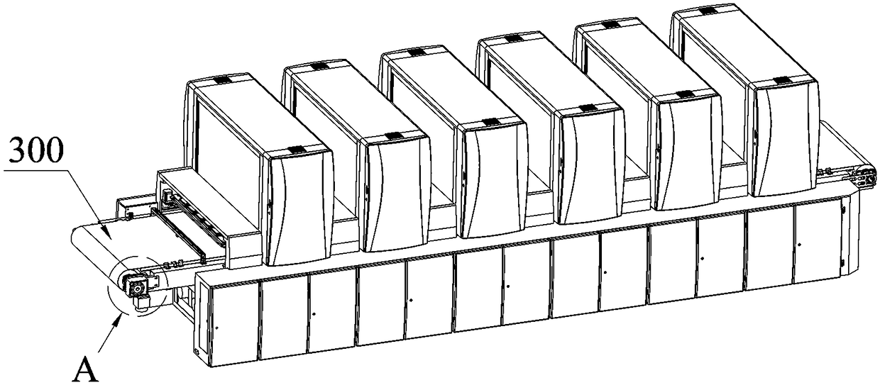
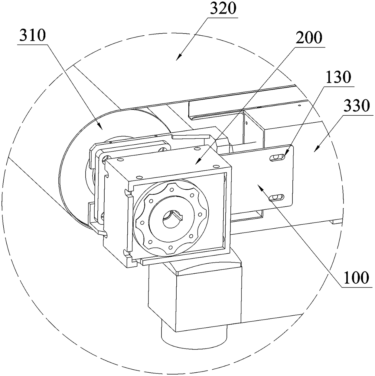
[0024] Such as Figure 1~2 As shown, a reducer 200 installation structure is used to fix the reducer 200 on the working machine, including a mounting plate 100, one end of the mounting plate 100 is connected to the reducer 200, and the other end is connected to the working machine, the reducer 200 is rotationally connected with the working machine.

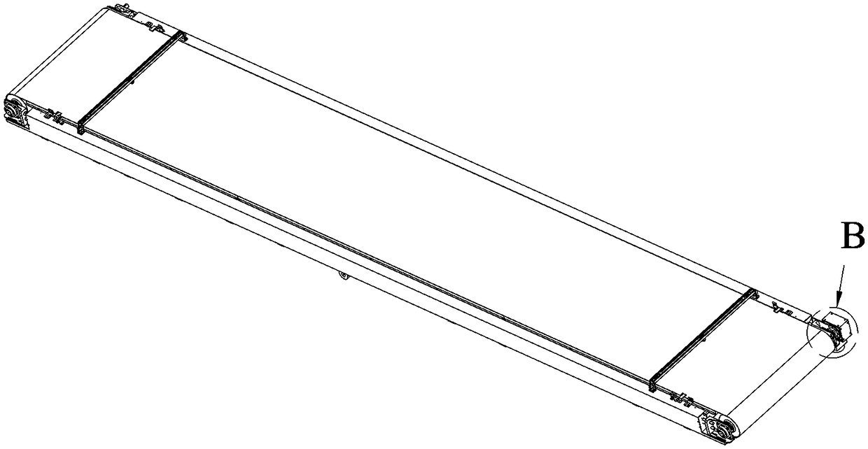
[0025] In this embodiment, the installation structure of the reducer 200 is used for the installation of the reducer 200 on the conveying platform 300 of the printer. The conveying platform 300 includes a driving roller shaft 310 and a driven roller shaft arranged in parallel, and a conveyor belt tightly sleeved on the roller shaft. 320 and the supporting part 330 for supporting the roller shaft, the reducer 200 is fixed on the supporting part 330 through the mounting plate 100 instead of being directly fixed on the supporting part 330, because the rigidity of the mounting plate 100 is much smaller than that of the supporting part...

Embodiment 2

[0031] The difference between this embodiment and Embodiment 1 is that the thickness of the mounting plate 100 is 3mm. Others are the same as embodiment 1.

Embodiment 3

[0033] The difference between this embodiment and Embodiment 1 is that the thickness of the mounting plate 100 is 10 mm. Others are the same as embodiment 1.


PUM


Abstract

The invention relates to the field of printing equipment, and discloses an installing structure of a speed reducer. The installing structure is used for fixing the speed reducer to a working machine and comprises an installing plate, one end of the installing plate is connected with the speed reducer, the other end of the installing plate is connected with the working machine, and the speed reducer is rotationally connected with the working machine. The speed reducer is fixedly connected to the working machine through the installing structure of the speed reducer, and therefore the circumferential movement of the whole speed reducer is limited, the coaxiality requirement for matched connection of an output shaft of the speed reducer and a driving shaft of the working machine in the assembling process can be reduced, the assembling difficulty can be reduced, the assembling efficiency can be improved, and the speed reducer can be effectively prevented from being damaged.

Description

technical field [0001] The present invention relates to the field of printing equipment, and more specifically, relates to a speed reducer installation structure. Background technique [0002] Industrial printers are used for inkjet printing on large-sized printing media such as ceramic tiles, wood boards, glass, corrugated paper, and buckle boards. Inkjet inkjet methods are used to inkjet inks of various colors on the printing media and then further process to obtain the expected pattern. During the printing process, the ink penetrates into the inside of the printing medium through corrosion, so that the pattern obtained by inkjet printing is not easy to fade, and has the characteristics of waterproof, UV protection, and scratch resistance. [0003] Inks of different colors or solvents with different functions are ejected through different nozzle modules, and the order in which inks of different colors and solvents with different functions are sprayed onto the printing medi...

Claims


Application Information

Patent Timeline
Patent Type & Authority Patents(China)
IPC IPC(8): B41J23/02B41J11/00
CPCB41J11/007B41J23/02
Inventor 万弋林
Owner 驱动数码电子(广东)有限公司
Why Eureka
Try Eureka