Ventilator humidifier and respiratory humidification treatment device

A humidifier and ventilator technology, which is applied in the field of ventilator humidifiers and respiratory humidification treatment devices, can solve the problem of increasing power consumption, increasing the risk of humidification fluid flowing back into the ventilator or tilting leakage, and difficult to prevent backflow And other issues

Pending Publication Date: 2017-09-19
HUNAN MICOME ZHONGJIN MEDICAL SCI & TECH DEV CO LTD
View PDF8 Cites 6 Cited by
  • Summary
  • Abstract
  • Description
  • Claims
  • Application Information

AI Technical Summary

Problems solved by technology

[0004] This heating method has great disadvantages. To improve the humidification capacity, the working temperature of the heating plate must be increased. Because it heats the liquid in the heating water tank as a whole, it will inevitably increase power consumption, and even the power consumption of the humidifier is greater than that of the humidifier. Power consumption of the ventilator
In order to facilitate maintenance, the traditional humidification water box structure often adopts an opening or a wide mouth, which is difficult to prevent backflow, which increases the risk of humidification fluid flowing backward into the ventilator or tilting to leak

Method used


Image

  • Ventilator humidifier and respiratory humidification treatment device
  • Ventilator humidifier and respiratory humidification treatment device
  • Ventilator humidifier and respiratory humidification treatment device

Examples


Embodiment Construction

[0025] The core of the present invention is to provide a ventilator humidifier, which has lower power than traditional humidifiers.

[0026] In order to enable those skilled in the art to better understand the technical solution of the present invention, the ventilator humidifier and respiratory humidification treatment device of the present application will be described in detail below in conjunction with the drawings and specific implementation methods.

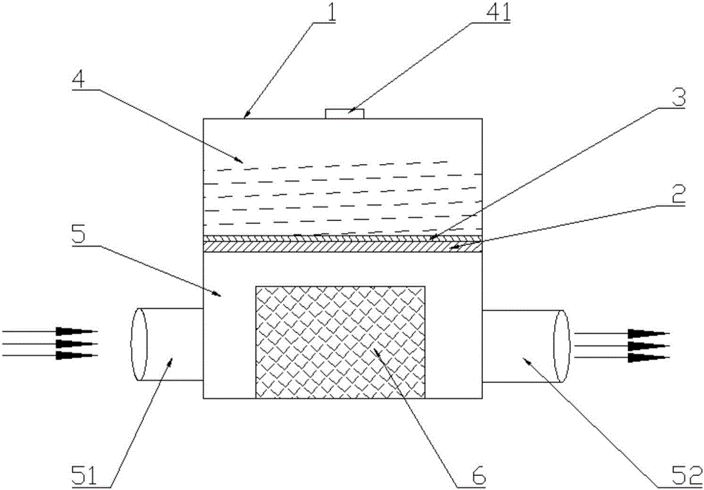
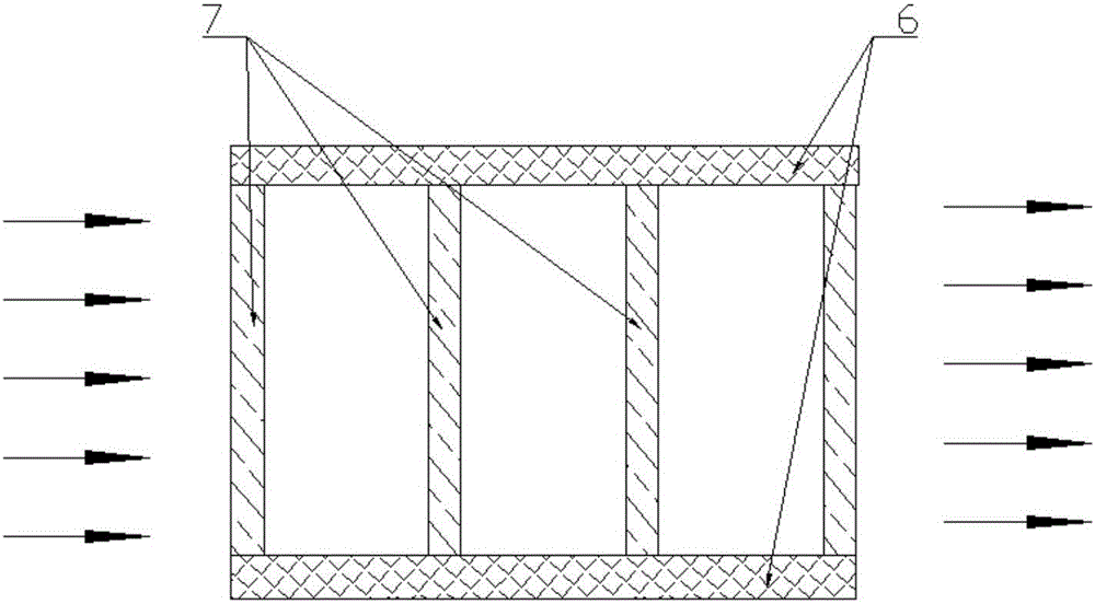
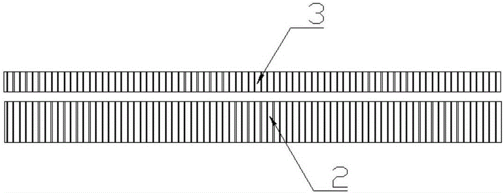
[0027] like figure 1 As shown, it is a structural schematic diagram of a specific embodiment of the ventilator humidifier provided in this application, and the arrows indicate the direction of gas flow. It includes a shell 1 with a hollow interior, and a water diversion plate 2 is arranged horizontally in the shell 1. The water divider 2 is fixedly connected with the inner wall of the shell 1, and divides the shell 1 into two independent cavities, the upper and the lower. Above the water dividing plate 2 is the water stora...


PUM


Abstract

The invention discloses a ventilator humidifier. The humidifier includes an outer shell with an inner hollow, and a water diversion plate divides the outer shell into two independent upper and lower cavities, wherein the upper cavity is a water storage chamber for storing humidifying liquid, and the lower cavity is a humidifying chamber used for evaporating and vaporizing; the plate surface of the water diversion plate is uniformly provided with a fine passage for water to flow downward, and a water control component is arranged above the water diversion plate; the side wall of the humidifying chamber is provided with an air inlet and an air outlet, and an evaporation device is used for heating the humidifying liquid which drips from the upside; the humidifying liquid is heated and evaporated in the humidifying chamber to be mixed with oxygen entering from the air inlet and humidify the dry oxygen. The evaporation device only needs to heat a micro amount of water dripping through the water diversion plate, so that only a small amount of heat needs to be provided to evaporate the micro amount of water so as to achieve the purpose of saving energy. The humidifying chamber and the water storage chamber are isolated from each other, and even if sloshing occurs, the humidifying liquid cannot flow back into an air outlet pipe. The invention also provides a respiratory humidification treatment device which includes the above ventilator humidifier, and the device can achieve the same technical effects.

Description

technical field [0001] The invention relates to the technical field of medical equipment, and further relates to a ventilator humidifier. In addition, the present application also relates to a respiratory humidification treatment device comprising the above-mentioned ventilator humidifier. Background technique [0002] When the ventilator is used alone to treat respiratory diseases, the ventilator outputs dry gas, and the patient is prone to side effects such as dry nose and throat, tongue pain, and even nosebleeds. The humidifier of the ventilator can increase the humidity of the gas entering the lungs, and the additional moisture can make up for the dry tissues of the nose and throat, prevent the above problems from occurring, and make patients feel more relaxed and comfortable breathing. [0003] The current ventilator humidifier heats the humidification liquid in the water box through a heating plate, and the heating plate is installed at the bottom of the heating water...

Claims


Application Information

Patent Timeline
Patent Type & Authority Applications(China)
IPC IPC(8): A61M16/16
CPCA61M16/0003A61M16/162A61M2205/33A61M2205/3368A61M2202/0208A61M2202/0007
Inventor 戴征丁锦李伟利刘炜徐勤鹏
Owner HUNAN MICOME ZHONGJIN MEDICAL SCI & TECH DEV CO LTD
Why Eureka
Try Eureka