Eureka AIR delivers breakthrough ideas for toughest innovation challenges, trusted by R&D personnel around the world.

a mold

A mold and mold cavity technology, applied in the field of molds injected with fluid medium, can solve the problem that the mold setting space is difficult to meet the requirements of injection molding operations, and achieve the effect of reducing the difficulty of combination, alleviating the degree of urgency, and reducing the cost of mold opening.

Active Publication Date: 2020-04-17
MODERN PRECISION PLASTIC & MOLD SHENZHEN CO LTD
View PDF9 Cites 0 Cited by
  • Summary
  • Abstract
  • Description
  • Claims
  • Application Information

AI Technical Summary

Problems solved by technology

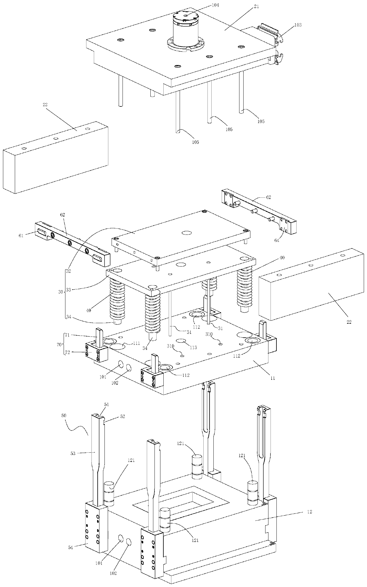
[0005] The object of the present invention is to provide a mold, which aims to solve the problem that the mold setting space in the injection mold in the prior art is difficult to meet the injection molding operation requirements

Method used


Image

  • a mold
  • a mold
  • a mold

Examples


Embodiment Construction

[0053] In order to make the object, technical solution and advantages of the present invention clearer, the present invention will be further described in detail below in conjunction with the accompanying drawings and embodiments. It should be understood that the specific embodiments described here are only used to explain the present invention, not to limit the present invention.

[0054]It should be noted that when an element is referred to as being “fixed” or “disposed on” another element, it may be directly on the other element or be indirectly on the other element. When an element is referred to as being "connected to" another element, it can be directly connected to the other element or indirectly connected to the other element.

[0055] It should also be noted that the orientation terms such as left, right, up, and down in this embodiment are only relative concepts or refer to the normal use state of the product, and should not be regarded as limiting.

[0056] Such as...


PUM


Abstract

The invention provides a mold. The mold comprises a first half mold and a second half mold. The mold further comprises an ejector pin mechanism traction device. The ejector pin mechanism traction device comprises an installation and fixation assembly, an ejector pin connection assembly, an elastic element, a guide buckling assembly, a clamping assembly and a guide unlocking assembly. The installation and fixation assembly is fixedly connected with the first half mold. When the ejector pin connection assembly is close to the first half mold, the ejection out end of the ejector pin penetrates through the first half mold. The guide buckling assembly is connected to the second half mold. The clamping assembly is connected to the ejector pin connection assembly. A clamping protruding block of the clamping assembly cooperates with a buckling bayonet to form lock. The guide unlocking assembly is connected to the first half mold. A guide block of the guide unlocking assembly is arranged in the guide groove in a matched manner. An unlocking structure is arranged between the guide block and the buckling protruding block so as to achieve unlocking of the buckling protruding block and the buckling bayonet. By the adoption of the mold, the problem that in the prior art, the mold arrangement space of an injection mold can hardly meet injection molding operation requirements is solved.

Description

technical field [0001] The invention relates to the technical field of production and processing equipment, in particular to a mold for molding by injecting a fluid medium, which can be used for molding resin and rubber. Background technique [0002] In the injection molding production process, after the injection molding material is injected into the cavity, the mold needs to be split. During the splitting process, the injection molded part is usually attached to one half of the mold (due to the adhesion design, the injection molded part Attached to a set half-mold), usually the adhesion between the injection molded part and the mold is relatively large, and it is necessary to use external force to demould the injection molded part and the mold. The thimble mechanism is a commonly used mechanism for demoulding injection molded parts and molds. The thimble mechanism usually uses cylinder power mechanism, oil cylinder power mechanism, motor power mechanism, mechanical linkage...

Claims


Application Information

Patent Timeline
Patent Type & Authority Patents(China)
IPC IPC(8): B29C45/26B29C45/66B29C45/40
CPCB29C45/2602B29C45/2606B29C45/4005B29C45/66B29C2045/2604
Inventor 黄中明
Owner MODERN PRECISION PLASTIC & MOLD SHENZHEN CO LTD
Why Eureka
Eureka Blog
Learn More