Guides for nuclear fuel pellet loading

A guiding device and nuclear fuel technology, applied in nuclear engineering, nuclear power generation, greenhouse gas reduction, etc., can solve problems such as difficult installation, low efficiency, and easy scratches on the outer surface of nuclear fuel pellets, so as to improve the degree of automation and improve The effect of loading speed

Active Publication Date: 2019-01-29
彭州市长庆全成技术开发有限公司
View PDF11 Cites 0 Cited by
  • Summary
  • Abstract
  • Description
  • Claims
  • Application Information

AI Technical Summary

Problems solved by technology

[0005] The purpose of the present invention is to provide a guide device for nuclear fuel pellet filling, which solves the problem that during manual filling, due to the small gap between the nuclear fuel pellet and the inner hole of the cladding tube, it is difficult to load it during assembly, the efficiency is too low, and The problem of easily scratching the outer surface of nuclear fuel pellets

Method used


Image

  • Guides for nuclear fuel pellet loading
  • Guides for nuclear fuel pellet loading
  • Guides for nuclear fuel pellet loading

Examples


Embodiment 1

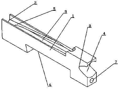
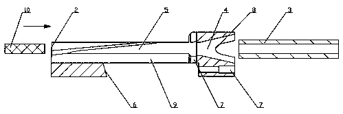
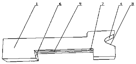
[0034] Such as figure 1 , 2 As shown in and 3, the guide device for nuclear fuel pellet filling includes a guide block 1, the front end side wall of the guide block 1 is provided with a material inlet 2, and the rear end side wall of the guide block 1 is provided with a The cladding tube 3 communicates with the trumpet-shaped discharge port 4, the feed port 2 and the discharge port 4 are connected through the guide chute 5 opened, and the feed port 2, the guide chute 5 and the discharge port 4 constitute A straight-line pellet guide channel is established; along the direction from the inlet 2 to the outlet 4, the diameter of the trumpet-shaped outlet 4 gradually becomes larger, and the bottom of the guide chute 5 is also provided with a guide groove 9. The groove 9 is opened from the material inlet 2 to the material outlet 4 and opened to the material outlet 4, and the side wall of the guide groove 9 and the groove bottom of the guide chute have an arc transition. In this emb...

Embodiment 2

[0036] Such as figure 1 , 2 As shown in and 3, compared with embodiment 1, this embodiment optimizes the guide block 1, and the guide block 1 is also provided with a fixed groove 6, the fixed groove 6 is located below the guide chute 5, and the notch of the fixed groove 6 faces Next, in this embodiment, the fixing groove 6 enables the guide block 1 to be clamped on the support, thereby preventing the guide block 1 from shaking during work.

Embodiment 3

[0038] Such as figure 1 and 2 As shown, compared with Embodiment 2, the present embodiment optimizes the guide chute 5, and there is a screw positioning through hole 7 between the groove bottom of the guide chute 5 and the groove top of the fixed groove 6; the groove bottom of the guide chute 5 There is also a guide groove 9 between the groove top of the fixing groove 6. In this embodiment, through the screw positioning through hole 7, the guide block 1 can be further stably fixedly connected to the support, thereby avoiding the During operation, the shaking of the guide block 1 affects the entry of the nuclear fuel pellets into the cladding tube 3 , and the guide groove 9 can move the nuclear fuel pellets 10 more stably along the guide chute 5 .


PUM


Abstract

The invention discloses a guiding device for filling nuclear fuel pellets. The guiding device comprises a guide block, a feed port is formed in the side wall of the front end of the guide block, a trumpet-shaped discharge port communicating with a cladding tube is formed in the side wall of the back end of the guide block, the feed port is communicated with the discharge port through an opened guide chute, and the feed port, the guide chute and the discharge port form a linear type pellet guide channel; in a direction from the feed port to the discharge port, the caliber of the trumpet-shaped discharge port gradually becomes larger; and a guide groove is formed in the bottom of the guide chute, and is formed from the feed port to the discharge port, and a side wall of the guide groove and the bottom of the guide chute are in circular arc transition. The guiding device disclosed by the invention has the beneficial effects that the nuclear fuel pellets can automatically enter the cladding tube very quickly and conveniently, and the outer surfaces of the nuclear fuel pellets can be prevented from being scratched during filling, so that the filling speed and the automation degree of filling are improved.

Description

technical field [0001] The invention relates to a guide device, in particular to a guide device for nuclear fuel pellet filling. Background technique [0002] In the nuclear power plant fuel assembly manufacturing plant, nuclear fuel pellets are an important process in the tube loading process in the manufacture of fuel assembly single rods. [0003] At present, our country still adopts manual block matching, which has low production efficiency, cumbersome operation, poor working conditions for workers, and the measurement accuracy is affected by human factors, and it is difficult to realize the automation of tube loading. [0004] At the same time, when manual loading is used, because the technicians manually load the nuclear fuel pellets into the cladding tube, and the gap between the nuclear fuel pellets and the inner hole of the cladding tube is too small, it is difficult to load them during assembly, and the efficiency is too low , and it is easy to scratch the outer s...

Claims


Application Information

Patent Timeline
Patent Type & Authority Patents(China)
IPC IPC(8): G21C21/02
CPCG21C21/02Y02E30/30
Inventor 刘超刘华梁效玉
Owner 彭州市长庆全成技术开发有限公司
Why Eureka
Try Eureka