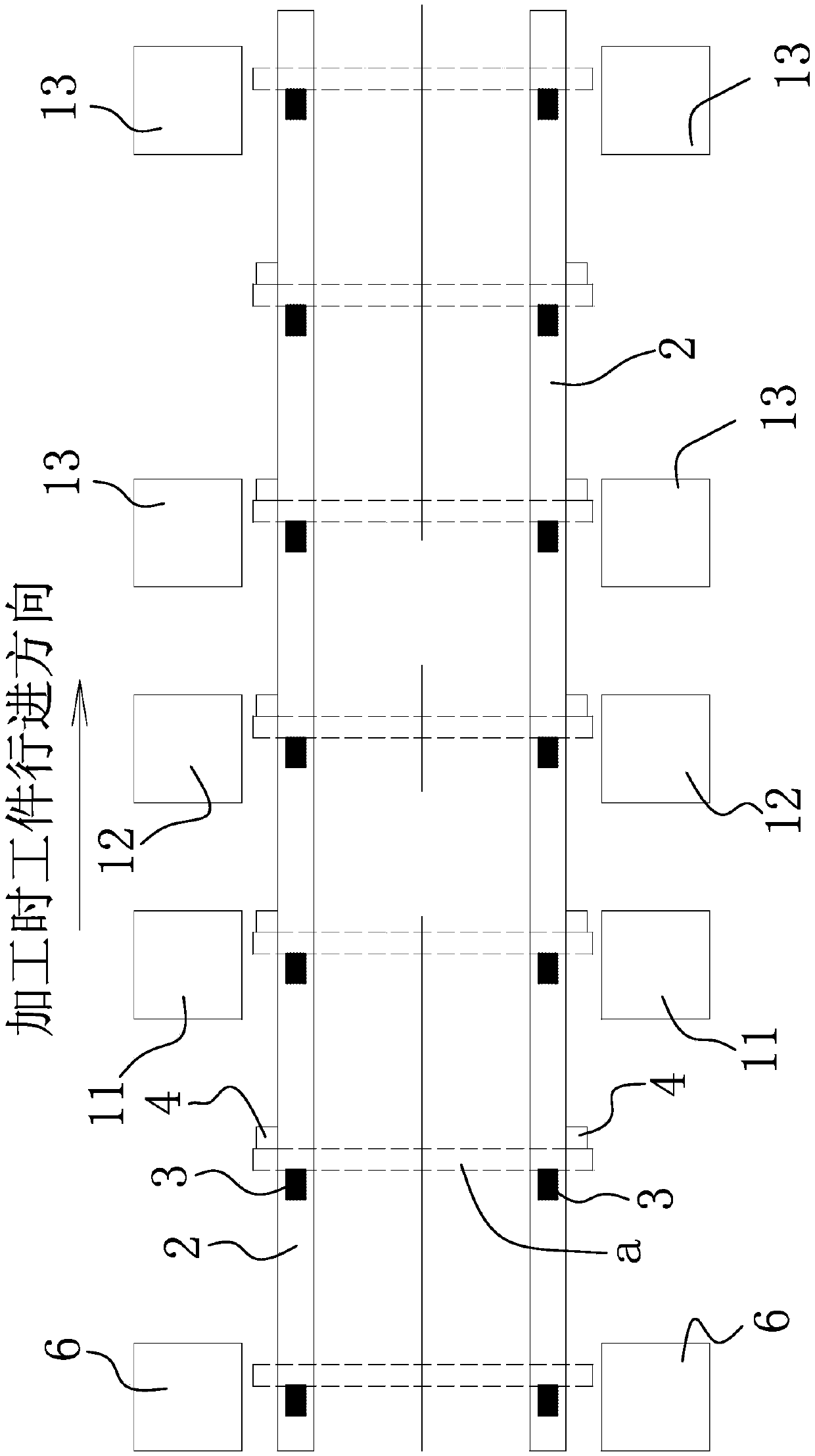
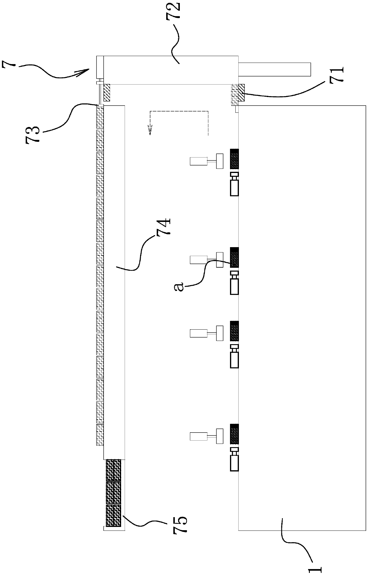
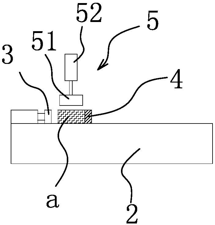
Double-end feeding tenon planting equipment

A feeding, double-end technology, applied in the field of double-end feeding tenoning equipment, can solve the problems of unguaranteed machining accuracy, unsolved technical problems, inaccurate positioning, etc., to achieve simple and reliable control, improve practicability, and reduce manufacturing costs. Effect

Active Publication Date: 2019-04-16
JIASHAN QUANSHENG AUTOMATION MACHINERY
View PDF9 Cites 0 Cited by
  • Summary
  • Abstract
  • Description
  • Claims
  • Application Information

AI Technical Summary

Problems solved by technology

This method has the following technical problems: when moving from the previous station to the next station, its positioning is inaccurate and the machining accuracy cannot be guaranteed. Secondly, the control of the feeding of the tenon requires at least two cylinders, and its cost is relatively high. high, poor usability
[0004] Although the above-mentioned solution has many advantages above, the above-mentioned solution does not solve the above-mentioned technical problems. Therefore, it is urgent to design a double-end feeding tenon planting equipment that can solve the above-mentioned technical problems.

Method used


Image

  • Double-end feeding tenon planting equipment
  • Double-end feeding tenon planting equipment
  • Double-end feeding tenon planting equipment

Examples


Embodiment 2

[0113] Such as Figure 8-11 As shown, the structure and principle of this embodiment are basically the same as those of Embodiment 1, so we won’t repeat them here. The difference lies in:

[0114] The lower tenon control mechanism 8 includes a lower tenon tube 82 arranged obliquely. The lower end of the lower tenon tube 82 is connected with a tenon planting seat 86 with a tenon silo 861 . The sliding block 87 that moves horizontally and has a wooden tenon receiving groove 871, the sliding block 87 is connected with the translation drive structure and when the wooden tenon receiving groove 871 on the sliding block 87 is aligned with the lower end of the lower tenon tube 82, the wooden The tenon receiving groove 871 receives the wooden tenon b output from the lower end of the lower tenon tube 82, and a tenon planting guide hole 862 connected with the tenon planting base 86 is provided on the tenon planting base 86, and a tenon planting guide hole 862 connected with the tenon pla...


PUM


Abstract

The invention provides double-end feeding and tenon planting equipment. The double-end feeding and tenon planting equipment comprises a rack and two conveyor belts, and the two conveyor belts are symmetrically arranged on the rack. Drilling units, glue spraying units and tenon planting units are sequentially arranged on the rack in the conveying direction of the conveyor belts. A plurality of flexible stop points are arranged on each conveyor belt at intervals in the circumferential direction of the conveyor belt. The flexible stop points on the two conveyor belts are symmetrically arranged in pairs. When workpieces to be subjected to tenon planting are transversely arranged on the two conveyor belts, the flexible stop points symmetrically arranged in pairs push the workpieces to be subjected to tenon planting to move in the conveying direction of the conveyor belts. At least three lifting stop points in one-to-one correspondence to the drilling units, the glue spraying units and the tenon planting units are arranged on each conveyor belt, and the lifting stop points on the two conveyor belts are symmetrically arranged in pairs. When the workpieces to be subjected to tenon planting move to set positions in the conveying direction of the conveyor belts, the lifting stop points and the flexible stop points clamp the corresponding workpieces to be subjected to tenon planting. A tenon discharge control mechanism capable of outputting tenons to the tenon planting units one by one is further arranged on the rack.

Description

technical field [0001] The invention belongs to the technical field of wood processing, and in particular relates to a double-end feeding tenon planting device. Background technique [0002] In the operation of the traditional automatic drilling machine, several clamps are set on the conveyor belt. When performing a series of processing, the clamps are always clamped to realize one by one processing. This method has the following technical problems: when moving from the previous station to the next station, its positioning is inaccurate and the machining accuracy cannot be guaranteed. Secondly, the control of the feeding of the tenon requires at least two cylinders, and its cost is relatively high. High, poor practicality. [0003] In order to solve the above-mentioned technical problems, for example, Chinese patent literature discloses a dual-station automatic drilling and tenoning machine [application number: 201610899841.X], which includes a frame on which a feeding devi...

Claims


Application Information

Patent Timeline
Patent Type & Authority Patents(China)
IPC IPC(8): B27F4/00B27G11/00B27C3/00
CPCB27C3/00B27F4/00B27G11/00
Inventor 苏冬梅
Owner JIASHAN QUANSHENG AUTOMATION MACHINERY
Why Eureka
Try Eureka