Laser projection system and method

A laser projection and laser projector technology, which is applied to stereo systems, components of TV systems, and optical devices, etc., can solve the problems of unusable mass production of projection templates and limited opportunities to project geometrically accurate projected images, etc. Achieve low cost, improve quality and dimensional accuracy, and reduce costs

Active Publication Date: 2013-09-25
VIRTEK VISION INT ULC
View PDF5 Cites 17 Cited by
  • Summary
  • Abstract
  • Description
  • Claims
  • Application Information

AI Technical Summary

Problems solved by technology

However, projection templates are also not available for mass production, where various workpieces are produced, and opportunities to project geometrically accurate projected images are limited

Method used


Image

  • Laser projection system and method
  • Laser projection system and method
  • Laser projection system and method

Examples


Embodiment Construction

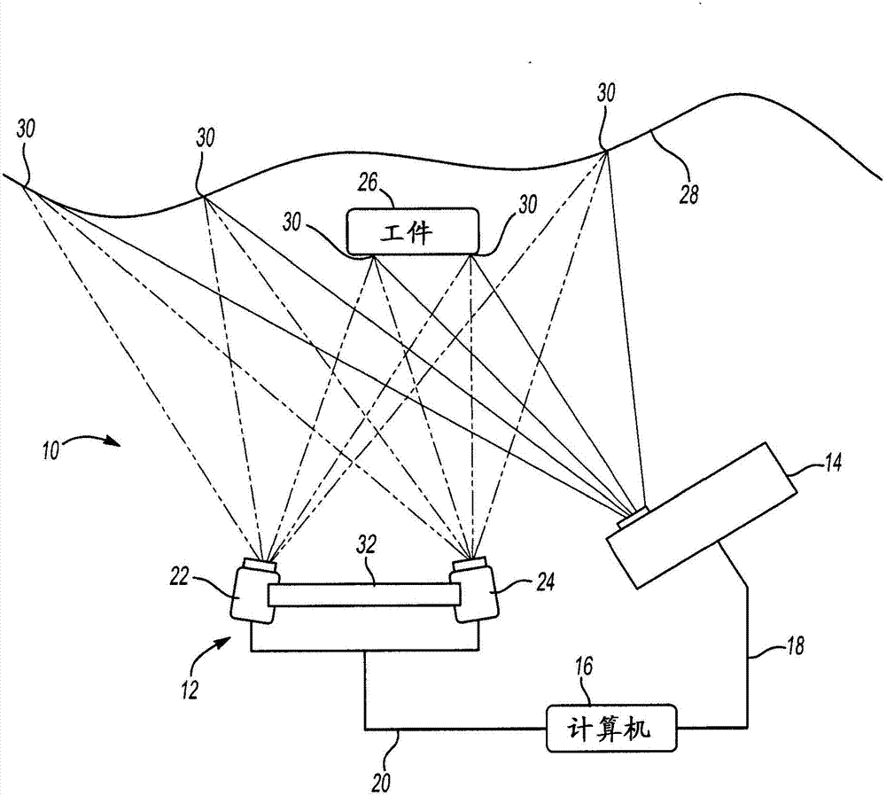
[0015] figure 1 A laser projection system for projecting an image on a workpiece is generally shown at 10 . The laser projection system includes a photogrammetric assembly 12 and a laser projector 14 each in communication via a computer 16 . Computer 16 communicates with laser projector 14 via circuitry 18 and with photogrammetry assembly 12 via circuitry 20 . Although the circuits 18, 20 are shown as hardwired in this example, those skilled in the art will appreciate that radio frequency or equivalent transmissions between the computer 16, photogrammetry assembly 12, and laser projector 14 are also within the scope of the present invention. within range.

[0016] The photogrammetry assembly includes a first camera 22 and, in this embodiment, a second camera 24 . The inventor contemplates that an alternative embodiment may use only the first camera 22, as will be explained below. One type of camera that comes to the mind of the inventor is an industrial camera manufactured...


PUM


Abstract

A laser projection system for projecting an image on a workpiece includes a photogrammetry assembly and a laser projector, each communicating with a computer. The photogrammetry assembly includes a first camera for scanning the workpiece, and the laser projector projects a laser image to arbitrary locations. Light is conveyed from the direction of the workpiece to the photogrammetry assembly. The photogrammetry assembly signals the coordinates light conveyed toward the photogrammetry assembly to the computer with the computer being programmable for determining a geometric location of the laser image. The computer establishes a geometric correlation between the photogrammetry assembly, the laser projector, and the workpiece for realigning the laser image to a corrected geometric location relative to the workpiece.

Description

[0001] prior application [0002] This application claims priority to US Provisional Patent Application No. 61 / 614,252, filed March 22, 2012. technical field [0003] The present application relates generally to laser projection systems for use in industrial environments. More specifically, the application relates to projecting a laser template on a workpiece by means of a photogrammetric assembly. Background technique [0004] Photogrammetry processes and components have been used to identify the location of objects in a variety of settings. In some cases, photogrammetry has been found useful for the fabrication of semiconductors for use in computer-based objects. However, photogrammetry has not been proven useful for the fabrication of large-scale objects in a mass-production setting. [0005] Alternatively, laser projectors have been used to project assembly templates onto objects as an assembly aid in the manufacture of mass-produced products. However, projection tem...

Claims


Application Information

Patent Timeline
Patent Type & Authority Applications(China)
IPC IPC(8): G01B11/25H04N13/239
CPCG01C15/002G01B11/002G01B11/2545H04N13/239G01C11/025H04N13/254H04N23/00G01C11/00H04N9/3129G06T7/194G06T7/74G06T7/11B23Q17/2423G01B11/005G01C11/02G01C11/08G06T7/0006G06T7/001G06T2207/10012G06T2207/10028G06T2207/20224G06T2207/30164G06T2207/30204
Inventor K·D·鲁博
Owner VIRTEK VISION INT ULC
Why Eureka
Try Eureka