Hydraulic plug pin ascending device and descending device

A lifting device and hydraulic technology, applied in the field of self-elevating offshore platform accessories, can solve the problems of high manufacturing cost of the truss-type lifting device, and achieve the effects of low assembly accuracy, reduced manufacturing cost, and simple production

Active Publication Date: 2017-10-03
WUHAN MARINE MACHINERY PLANT
View PDF1 Cites 7 Cited by
  • Summary
  • Abstract
  • Description
  • Claims
  • Application Information

AI Technical Summary

Problems solved by technology

[0006] In order to solve the problem of high manufacturing cost of the truss type lifting device in the prior art, the embodiment of the present invention provides a hydraulic bolt lifting device

Method used


Image

  • Hydraulic plug pin ascending device and descending device
  • Hydraulic plug pin ascending device and descending device
  • Hydraulic plug pin ascending device and descending device

Examples


Embodiment

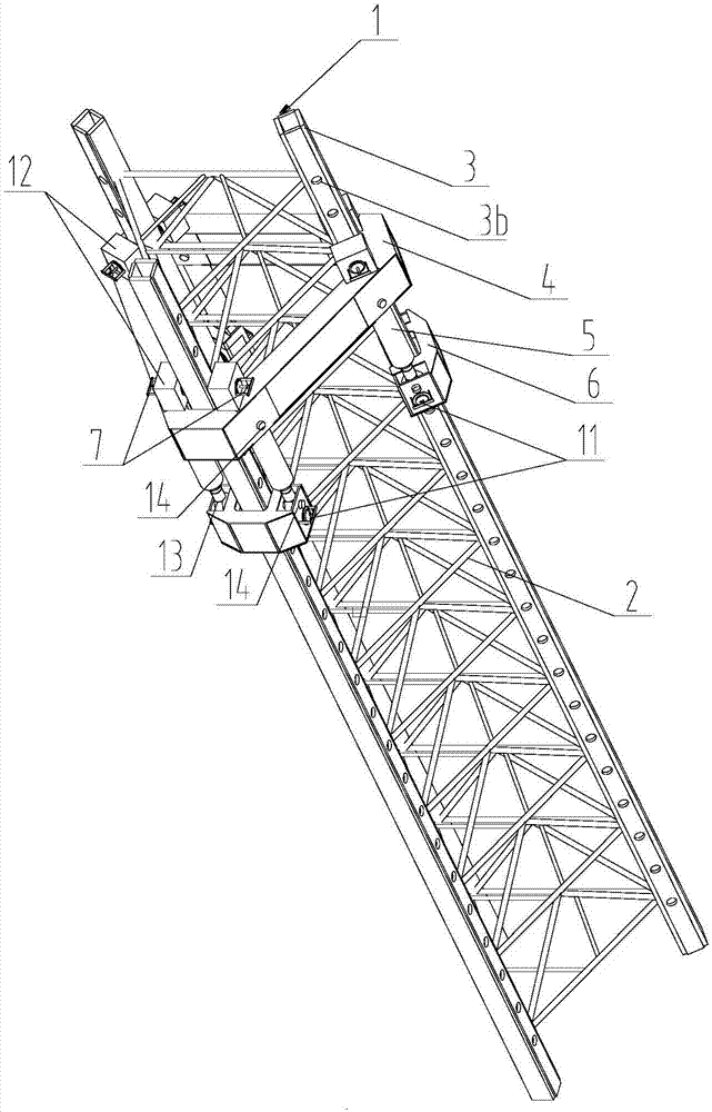
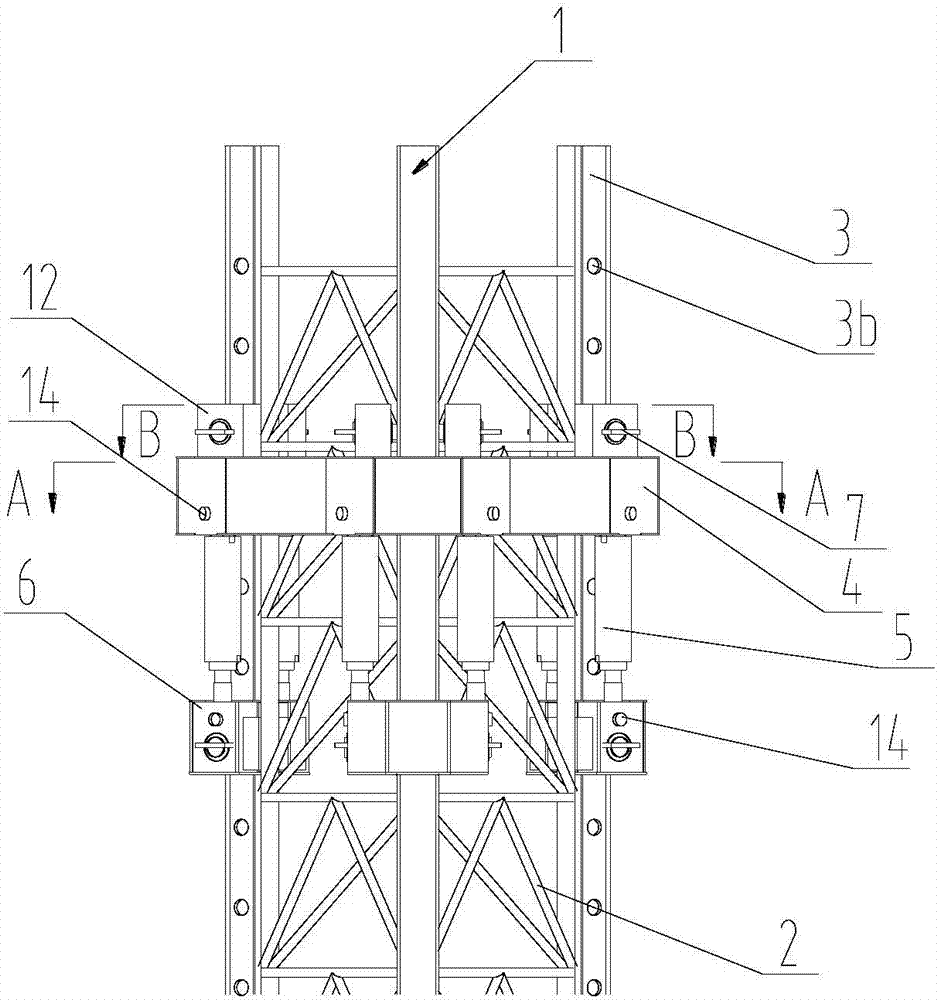
[0026] The embodiment of the present invention provides a hydraulic bolt lifting device, such as figure 1 and figure 2 As shown, the hydraulic bolt lifting device includes a truss-type leg 1. The truss-type leg 1 includes a truss structure 2 and three chords 3. The three chords 3 are not on the same plane and are arranged parallel to each other. The truss structure 2 is arranged on the three chords. Between 3, the hydraulic bolt lifting device also includes: a ring beam 4, a lifting cylinder 5, a sliding beam 6, a bolt assembly 7 and a bolt installation block 12.

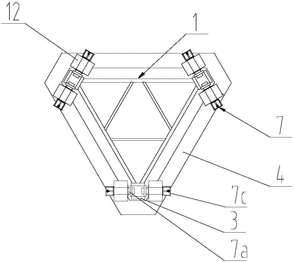
[0027] Each chord 3 is provided with a plurality of pin holes 3b matched with the pin assembly 7, and the multiple pin holes 3b are arranged along the length direction of the chord 3, and the ring beam 4 is slidably sleeved on the truss-type pile legs. 1 on. image 3 is a schematic diagram of the top view structure of the ring beam, combined with image 3 , a plurality of bolt mounting blocks 12 are installed on...


PUM


Abstract

The invention discloses a hydraulic plug pin ascending and descending device, and belongs to the field of self-ascending type ocean platform accessories. The hydraulic plug pin ascending and descending device comprises truss type pile legs, a ring beam, a lifting oil cylinder, a sliding beam, plug pin assemblies and plug pin mounting blocks; a plurality of plug pin holes which are matched with plug pin assemblies are uniformly formed in each chord rod; the plurality of plug pin holes are arranged in the length direction of each chord rod; the ring bean is arranged on the truss type pile legs in a sliding and sleeving manner; the plurality of the plug pin mounting blocks are respectively mounted on the ring beam; the plurality of the plug pin assemblies are respectively mounted on the respective corresponding plug pin mounting blocks; the plug pin assemblies and the plug pin holes are oppositely arranged at intervals; a plurality of sliding beams are respectively arranged on the respective corresponding chord rod in a sliding manner; one end of the lifting oil cylinder is mounted on the ring beam; the other end of the lifting oil cylinder is mounted on the sliding beam. The hydraulic plug pin ascending and descending device is low in assembling precision; the manufacturing cost is reduced.

Description

technical field [0001] The invention relates to the field of self-elevating offshore platform accessories, in particular to a hydraulic bolt lifting device. Background technique [0002] The lifting device is the key structure in the jack-up offshore platform, and its performance directly affects the safety performance, performance and economy of the jack-up offshore platform. [0003] The existing lifting device is mainly a truss type lifting device, and the truss type lifting device realizes the lifting operation of the self-elevating offshore platform through a rack and pinion. [0004] In the process of realizing the present invention, the inventor finds that there are at least the following problems in the prior art: [0005] In the existing truss-type lifting device, the installation and manufacturing accuracy of the rack and pinion is very high, which makes the truss-type lifting device have a high manufacturing cost. At the same time, the existing truss-type lifting...

Claims


Application Information

Patent Timeline
Patent Type & Authority Applications(China)
IPC IPC(8): E02B17/08
Inventor 程文池赵世琏陈佳俊朱正都田崇兴
Owner WUHAN MARINE MACHINERY PLANT
Why Eureka
Try Eureka