Urea pumping system

A technology of urea pump and urea tank, which is applied in the direction of exhaust gas treatment, machine/engine, mechanical equipment, etc. It can solve the problems of necessary compressed air source, easy crystallization of urea, complex structure, etc., and achieve good effect, low cost and stable pressure sex high effect

Pending Publication Date: 2017-10-13
HUST WUXI RES INST +1
View PDF5 Cites 8 Cited by
  • Summary
  • Abstract
  • Description
  • Claims
  • Application Information

AI Technical Summary

Problems solved by technology

[0004] The purpose of the present invention is to propose a new type of air-free urea pumping system to solve the problems of conventional urea pumping system with complex structure, easy crystallization of urea, serious blockage and necessary compressed air source

Method used


Image

  • Urea pumping system
  • Urea pumping system
  • Urea pumping system

Examples


Embodiment 1

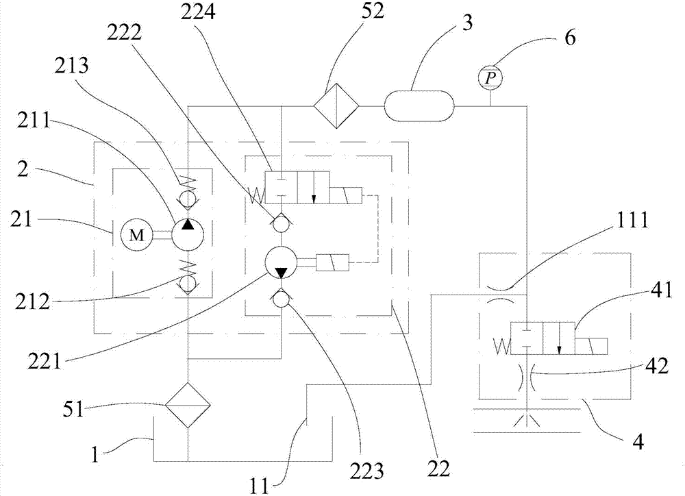
[0022] Such as figure 1 As shown, the urea pumping system in this embodiment includes a urea tank 1, a urea pump module 2, an accumulator 3, and a nozzle module 4 connected in sequence through pipelines, and the urea pump module 2 includes a parallel set for pumping urea The liquid in the tank 1 is pumped to the main pump 21 of the nozzle module 4 and the auxiliary pump 22 for reversely sucking the liquid in the pipeline back to the urea tank 1. The nozzle module 4 includes a first solenoid valve 41 and an atomizing nozzle , the first electromagnetic valve 41 is respectively connected to the accumulator 3 and the atomizing nozzle through pipelines, and the pipeline between the first electromagnetic valve 41 and the accumulator 3 is provided with a return pipeline 11 communicated with the urea tank 1, and the return pipe A first damping hole 111 is opened on the road 11 .

[0023] The main pump 21 transports the solution in the forward direction, and the auxiliary pump 22 reve...

Embodiment 2

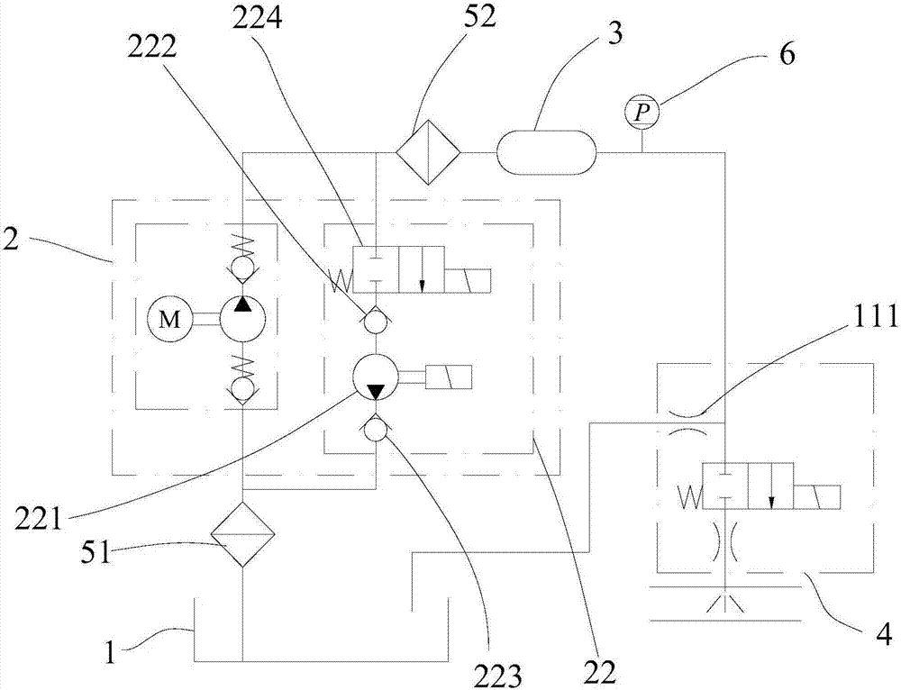
[0034] Such as figure 2 As shown, the main difference between this embodiment and Embodiment 1 is that the electromagnetically driven pump 221 and the second electromagnetic valve 224 are driven and controlled separately. All the other parts are identical to the structure of embodiment 1.

Embodiment 3

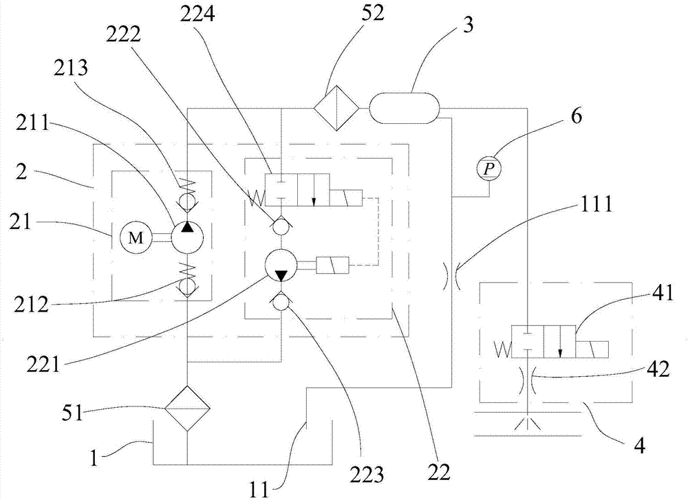
[0036] Such as image 3 As shown, the main difference between this embodiment and Embodiment 1 is that: the return pipeline 11 is arranged to be connected with the accumulator 3 , and the pressure sensor 6 is arranged on the return pipeline 11 . All the other parts are identical to the structure of embodiment 1.


PUM


Abstract

The invention discloses a urea pumping system. The urea pumping system comprises a urea box, a urea pump module, an energy accumulator and a nozzle module which are sequentially connected through a pipeline, wherein the urea pump module comprises a main pump used for pumping a liquid in the urea box to the nozzle module, and an auxiliary pump used for reversely sucking a liquid in the pipeline back into the urea box; the nozzle module comprises a first electromagnetic valve and an atomization nozzle; the first electromagnetic valve is connected with the energy accumulator and the atomization nozzle through the pipeline; a reflux pipeline which communicates with the urea box is arranged on the pipeline between the first electromagnetic valve and the energy accumulator; and a first damping hole is formed in the reflux pipeline. According to the urea pumping system, an airfree auxiliary structure is adopted, double-pump parallel connection is adopted, when a urea solution is injected, the main pump is started, the urea solution is pumped from the urea box to the nozzle module, after injection, the auxiliary pump sucks the urea solution remaining in the system back into the urea box, and the problems of urea crystallization and pipeline blocking are solved.

Description

technical field [0001] The present application relates to the technical field of post-treatment of diesel engine exhaust, in particular to an airless assisted urea pumping system. Background technique [0002] In-machine purification technology cannot fully meet the increasingly stringent emission standards, so it is necessary to install exhaust after-treatment devices on diesel engines. The current mainstream post-treatment technology is SCR technology, which uses urea solution as a reducing agent to purify nitrogen oxides in exhaust gas. The urea pumping system mainly includes: a urea tank for storing urea solution, a urea pump for pumping the urea solution in the urea tank into the exhaust pipe, a urea level sensor for detecting the liquid level in the urea tank, and preventing urea crystallization cooling water system. The air-assisted urea pumping system is widely used in the market, in which a compressed air source is added, and the compressed air is sprayed to clean...

Claims


Application Information

Patent Timeline
Patent Type & Authority Applications(China)
IPC IPC(8): F01N3/20
CPCF01N3/2066F01N3/208F01N2610/1433F01N2610/1486F01N2610/02
Inventor 杨曙东史有程刘银水牛壮牛国贤潘希伟杜广杰
Owner HUST WUXI RES INST
Why Eureka
Try Eureka