Detection and screening device for steel balls

A screening device and technology of steel balls, applied in sorting and other directions, can solve the problems of low screening accuracy of steel balls and few detection parameters.

Active Publication Date: 2017-10-20
ZHEJIANG XINGCHANG BEARING
8 Cites 12 Cited by

AI-Extracted Technical Summary

Problems solved by technology

[0004] The purpose of the present invention is to solve the problem of low steel ball screening accuracy and few detection parameters in the prior art, and now provides a steel ball det...

Method used

Wherein, the probe 101 of pneumatic measuring instrument is a standard custom-made probe, so the dimensional accuracy is higher when adopting pneumatic measuring instrument to measure, is connected by fastener 102 between probe 101 and trachea 103, convenient and quick when changing, by trachea The 103 connection is less affected by environmental factors, which is convenient for the size detection of steel balls of different sizes and different environments.
Wherein, through hole 82 is circular, regular triangle or regular quadrilateral, adopts circular in this embodiment, and circular is not only conv...

Abstract

The invention relates to the technical field of steel ball screening, particularly to a detection and screening device for steel balls. The detection and screening device for the steel balls comprises a box body, a feeding mechanism, a detection mechanism and a classifying and collection device, wherein after passing through the feeding mechanism, the steel balls continuously pass through the detection mechanism one by one, weight and size of the steel balls are synchronously analyzed through a pressure sensor and an air gauge in the detection mechanism, internal structures of the steel balls are checked through a flaw detector, and finally, the steel balls are screened and classified. According to the detection and screening device, more properties of the steel balls can be detected, the material, size and internal condition of the steel balls are comprehensively analyzed, and the steel balls are screened and classified more accurately at higher precision.

Application Domain

Sorting

Technology Topic

EngineeringPressure sensor +1

Image

  • Detection and screening device for steel balls
  • Detection and screening device for steel balls
  • Detection and screening device for steel balls

Examples

  • Experimental program(1)

Example Embodiment

[0024] The technical solutions of the present invention will be further described in detail below through specific embodiments in conjunction with the drawings.
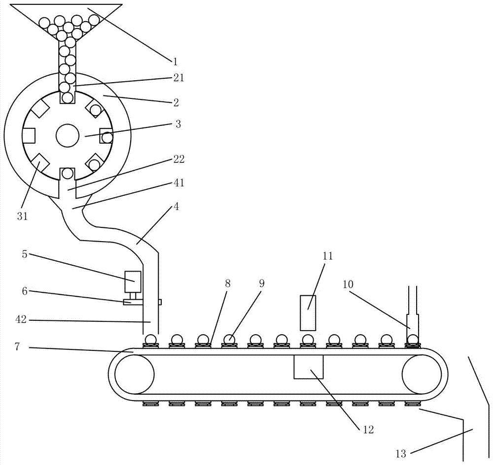
[0025] Such as Figure 1 to Figure 2 As shown, a steel ball detection and screening device includes a box body and a feeding mechanism. The feeding mechanism includes a feeding bin 1 fixed on the box body. The outlet of the feeding bin 1 is fixed on the box body. The upper end of the fixed disc ring 2 is provided with an upper through hole 21 that matches the outlet of the feed bin, and the fixed disc ring 2 is also provided with a lower through hole 22. The fixed disc ring 2 The inner sleeve is provided with a rotating disk 3 driven by a motor. The outer arc surface of the rotating disk 3 is provided with at least one hole 31. The hole 31 can only accommodate one steel ball 9, and the center of the hole 31 is The centers of the upper through hole 21 and the lower through hole 22 are on the same plane, the lower through hole 22 is fixedly connected to the feed end 41 of the feed pipe 4, and the discharge end 42 of the feed pipe is fixedly provided with a guide member 6, One end of the guide member 6 is fixedly connected with the piston rod of the cylinder 5 fixed on the box body, and the cylinder 5 is connected with the solenoid valve;
[0026] The detection mechanism includes a stepping motor, a conveyor belt 7 located at the lower end of the feeding tube driven by the stepping motor, and at least one clamping portion 8 is fixed on the conveyor belt 7, and the clamping portion 8 includes a fixed on the conveyor belt 7 on the fixing seat 84, the fixing seat 84 is fixedly provided with at least one pressure sensor 83, the pressure sensor 83 is provided with a support positioning portion 81 movably connected with the fixed seat 81, the support positioning portion 81 is in the middle The through hole 82 also includes a flaw detector probe 11 fixed above the middle of the conveyor belt 7, and a pneumatic measuring instrument detection part 10 fixed on the box is provided directly above the end of the conveyor belt 7, and it also includes a detection unit 10 located below the end of the conveyor belt 7. 的Classification receiving device 13.
[0027] Specifically, the steel ball 9 enters the clamping part 8 on the conveyor belt 7 through the feeding mechanism individually and intermittently, and is driven by the conveyor belt 7. When the steel ball 9 moves to the upper part of the supporting part 12 and the bottom of the flaw detector probe 11, the function of the stepping motor The pressure sensor 82 and the flaw detector 11 will feed back the quality data of the steel ball 9 and the internal condition data of the steel ball measured by the flaw detector 11 to the PLC. When the clamping part 8 moves on the conveyor belt 7 When reaching the detection part 10 of the pneumatic measuring instrument, the pneumatic measuring instrument 10 will transmit the measured diameter data of the steel ball 9 to the PLC. Under the action of the PLC, the measured data will be integrated and analyzed, and the steel ball 9 will be screened and classified as required .
[0028] Among them, the through hole 82 is a circle, a regular triangle or a regular quadrilateral. In this embodiment, a circle is used. The circle is not only convenient for processing, but also has a larger and more stable contact surface with the steel ball, and can also ensure that the center of gravity of the steel ball coincides with the center of the through hole. At the same time, the pressure sensors 83 are distributed at the top corners of the regular quadrilateral, and the data measured by the pressure sensors 83 are more accurate under the simultaneous action of the two structures.
[0029] Among them, the flaw detector is an ultrasonic flaw detector. The ultrasonic flaw detector has strong penetrating ability. It can detect the internal structure of the steel ball. It can select out the unqualified products such as cracks, looseness and pores that cannot be distinguished by the naked eye. Quality, ultrasonic flaw detector will not cause harm to human body.
[0030] Among them, the cylinder 5 is connected with the solenoid valve. Under the control of the PLC, the solenoid valve controls the cylinder 5 to move the piston rod, and the guide 6 moves downwards synchronously. At this time, the feed pipe 4 moves downwards and the steel ball The movement from the discharge end 42 of the feed pipe 4 to the clamping part 8 on the conveyor belt 7 is more precise and stable.
[0031] Wherein, the lower through hole 22 of the fixed ring disk 2 is located at the lowest position opposite to the upper through hole 21, and can be conveniently connected with the feed pipe 4 at this time.
[0032] Among them, the probe 101 of the pneumatic measuring instrument is a standard customized probe, so the dimensional accuracy is high when the pneumatic measuring instrument is used for measurement. The probe 101 and the trachea 103 are connected by a fastener 102, which is convenient and quick to replace. Environmental factors have little influence, and it is convenient to use for steel ball size detection of different sizes and different environments.
[0033] Among them, the sorting and receiving device is a number of Y-shaped grooves connected in series. At the bifurcation, a baffle controlled by a cylinder is provided to change the motion trajectory of the steel ball, and the solenoid valve controlled by the PLC determines the movement of the cylinder piston rod. The steel balls are classified according to the required parameter characteristics.
[0034] The above-mentioned embodiments are only preferred solutions of the present invention, and do not limit the present invention in any form. Other variations and modifications are possible without exceeding the technical solutions described in the claims.

PUM

no PUM

Description & Claims & Application Information

We can also present the details of the Description, Claims and Application information to help users get a comprehensive understanding of the technical details of the patent, such as background art, summary of invention, brief description of drawings, description of embodiments, and other original content. On the other hand, users can also determine the specific scope of protection of the technology through the list of claims; as well as understand the changes in the life cycle of the technology with the presentation of the patent timeline. Login to view more.
Why Eureka
Try Eureka