Method for processing turbine runner shaft

A processing method and turbine shaft technology, which is applied in the processing field of turbine shafts, can solve problems such as inconsistent tool wear, tool damage, and mass center offset, and achieve the effect of beautiful appearance and improved pass rate

Active Publication Date: 2009-04-15
CHONGQING JIANGJIN SHIPBUILDING IND
View PDF0 Cites 17 Cited by
  • Summary
  • Abstract
  • Description
  • Claims
  • Application Information

AI Technical Summary

Problems solved by technology

However, because the turbine blank flow channel is formed by pouring, affected by the pouring quality, the outer circle of the turbine is not concentric with the flow channel, causing the center of mass to shift. Therefore, after the three-claw clamps the outer circle of the turbine, only the end face can be aligned, but the turbine cannot be aligned. For the outer circle, the center hole at the small end of the optical axis and the mass center of the turbine are eccentric, which will inevitably cause the dynamic balance imbalance after processing in the subsequent process to be too large or exceed the specification requirements and be scrapped. Therefore, this processing method will cause the turbine shaft to fail. The rate is low, generally only about 50%. Moreover, even if the final product is qualified, more materials will be removed due to the need to correct the unbalanced amount, resulting in an unattractive final product.
On the other hand, when processing the R groove at the root of the turbine shaft, it is generally turned first and then relieved. However, since the turbine is made of high-temperature alloy material, and the optical shaft part is made of ordinary alloy material, the hardness of the R part of the welding part varies greatly. , while using a forming tool on an ordinary lathe to turn the R groove with 4 R connections, due to the large cutting contact surface between the tool and the part, the tool wear is inconsistent, and the tool is easy to be damaged, resulting in R dimensional accuracy and R smooth connection. It is not easy to guarantee , which is exactly the case, so when the shovel bed grinding wheel is shoveling, the grinding force of the grinding wheel will be uneven, and the sand grains of the grinding wheel will fall off unevenly. Finally, the dimensional accuracy of the R groove cannot be guaranteed, and the R joint is not a smooth connection, which is prone to stress Concentration; at the same time, because the shape of the R-shaped grinding wheel is trimmed by the designed R-shaped extrusion wheel, due to a long time, the extrusion wheel will be unevenly worn off by the grinding wheel, resulting in problems with the accuracy of the extrusion wheel itself. Therefore, the R shape of the parts is easy to go out of tolerance after a long time

Method used


Image

  • Method for processing turbine runner shaft
  • Method for processing turbine runner shaft

Examples


Embodiment 1

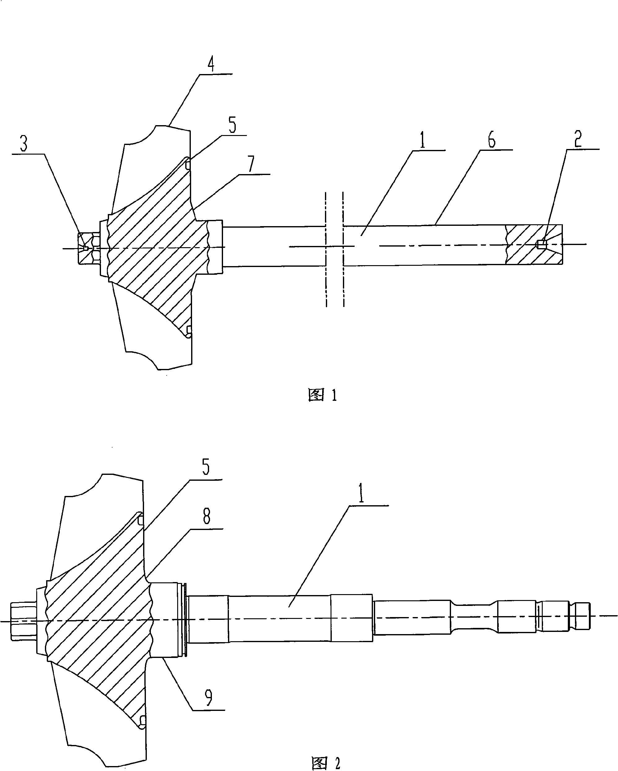
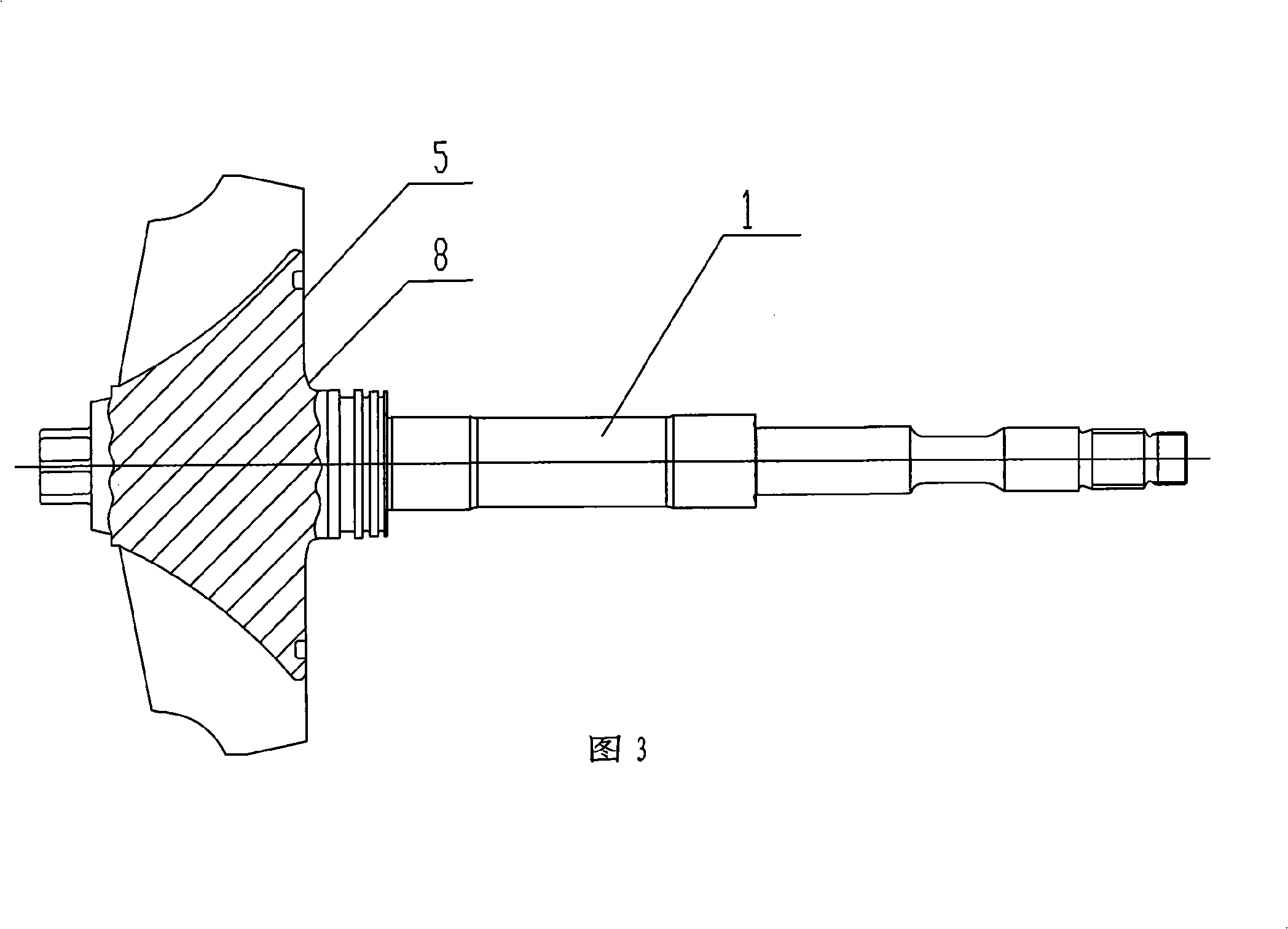
[0020] Embodiment 1: as shown in Fig. 1, Fig. 2 and Fig. 3, a kind of machining method of turbine shaft comprises the following steps: (1) rough turning the outer circle, light out the small end of the optical axis 1 and punch the center hole 2; (2) Coarse dynamic balance; (3) Correct the optical axis central hole 2 and the turbine end central hole 3 by eccentricity according to the coarse dynamic balance; (4) Take the corrected optical axis central hole 2 and the turbine end central hole 3 as the reference vehicle The outer circle of the optical axis is 6, the total length of the optical axis is taken with the center frame, and the center hole of the optical axis is re-drilled; (5) The center hole of the optical axis is used to semi-finish the outer circle of each level of semi-finishing; (6) Heat treatment and annealing; (7) Grinding Cutting the outer circle and end face of the turbine; (8) flaw detection inspection; (9) processing R groove 8 at the root of the turbine shaft;...


PUM


Abstract

The invention relates to a method for processing a turbine shaft. The key point of the invention is that the dynamic balancing method is applied after the outer circle of a rough turn optical axis and before the outer circle of a semi-refine turn optical axis to correct the center hole, so that the center hole and the outer circles of the optical axes are coincided with the mass center of the turbine. By the processing method, the qualified rate of the turbine shaft is more than 95 percent, and the appearance of a product is beautiful; simultaneously, by the method, the manufacturing accuracy of an R groove on the root part of the turbine shaft is greatly improved, and the processing difficulty is greatly reduced, thereby ensuring the R part to be coincided with the mass center of the turbine shaft and improving the performance of the turbine shaft.

Description

technical field [0001] The invention relates to a processing method for parts of mechanical equipment, in particular to a processing method for a turbine shaft. Background technique [0002] The existing processing method for the turbine shaft generally includes the following steps: 1. Rough turning to find the correct circle for the total length; 2. Semi-finishing the outer circle; 3. Heat treatment to remove welding stress; Repairing the center hole; 6. Grinding the outer circle and end face of the turbine; 7. Grinding the R groove at the root of the turbine shaft with a shovel; 8. Flaw detection; 9. Finishing the outer circle and end face of the car; 12. Repairing the center hole; 13. Grinding the outer circle of the center frame; 14. Drilling the end hole of the optical shaft and turning the thread; 15. Rough turning the piston ring groove; 16. Fine shovel grinding the piston ring groove; 17. Fine grinding Outer circle and end face; 18. Grinding the meridian surface of ...

Claims


Application Information

Patent Timeline
Patent Type & Authority Applications(China)
IPC IPC(8): B23P15/00G01M1/14B23B5/08
Inventor 段昌文曾凌云
Owner CHONGQING JIANGJIN SHIPBUILDING IND
Why Eureka
Try Eureka