Electric valve

An electric valve, valve body technology, applied in the direction of lift valve, valve details, valve device, etc., can solve the problems of shortened thread fit length, large gap between magnet and shell, and reduced output torque, etc., to achieve reduced valve needle swing, The effect of increasing wear resistance and reducing clearance

Inactive Publication Date: 2008-03-05
ZHEJIANG SANHUA CLIMATE & APPLIANCE CONTROLS GRP CO LTD
View PDF0 Cites 18 Cited by
  • Summary
  • Abstract
  • Description
  • Claims
  • Application Information

AI Technical Summary

Problems solved by technology

The system vibration frequency of the above structure (that is, the mechanical vibration caused by the vibration of the compressor when the refrigeration system where the valve is located, and the vibration of the system pipeline caused by the flow of refrigerant, and the vibration caused by the movement of the car in the vehicle system) In a small case, the influence is small, but this structure cannot meet the requirements under the high-frequency vibration of the system, especially when the valve is in the fully open position, the magnetic rotor moves to the upper end, the guide in the middle of the screw rod and the thread in the lower part The mating length becomes shorter, so it is easier to generate vibration
At the same time, due to the increase in the swing range of the screw, in order to prevent the magnet from colliding and rubbing against the housing, the gap between the magnet and the housing is required to be larger. Further, the gap between the outer coil and the magnet increases. Specifically, because the magnet and the housing are larger The gap reduces the volume or diameter of the magnet when the shell is determined, thereby reducing the output torque of the magnet when responding to or inducing the electromagnetic field of the coil), thus affecting the driving force of the product

Method used


Image

  • Electric valve
  • Electric valve
  • Electric valve

Examples


Embodiment Construction

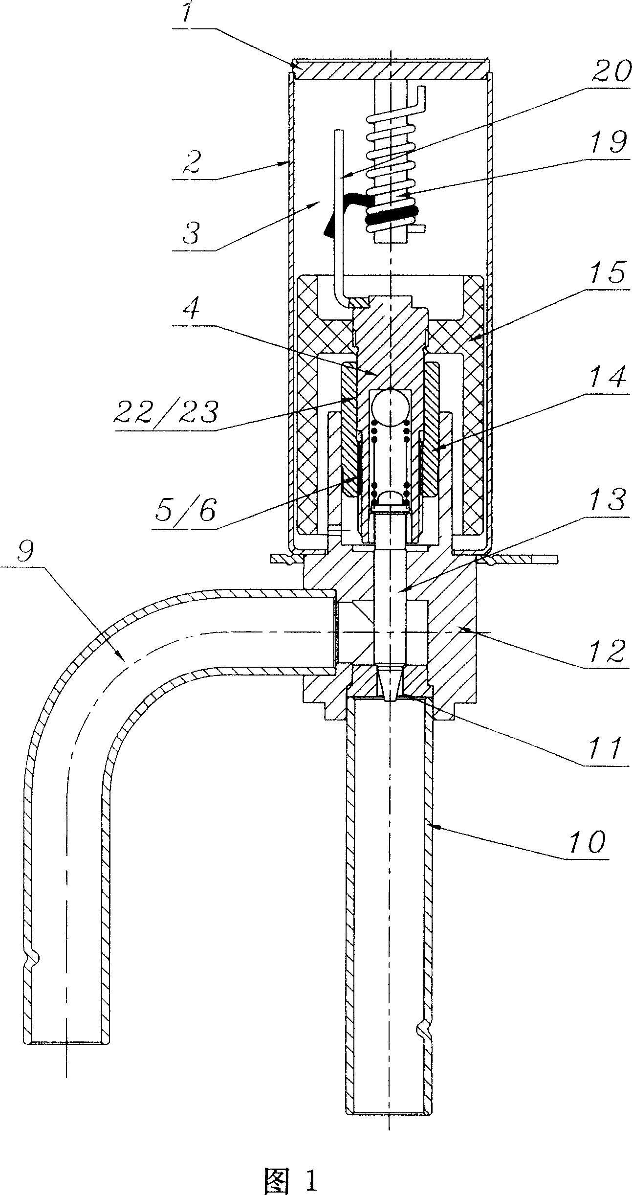
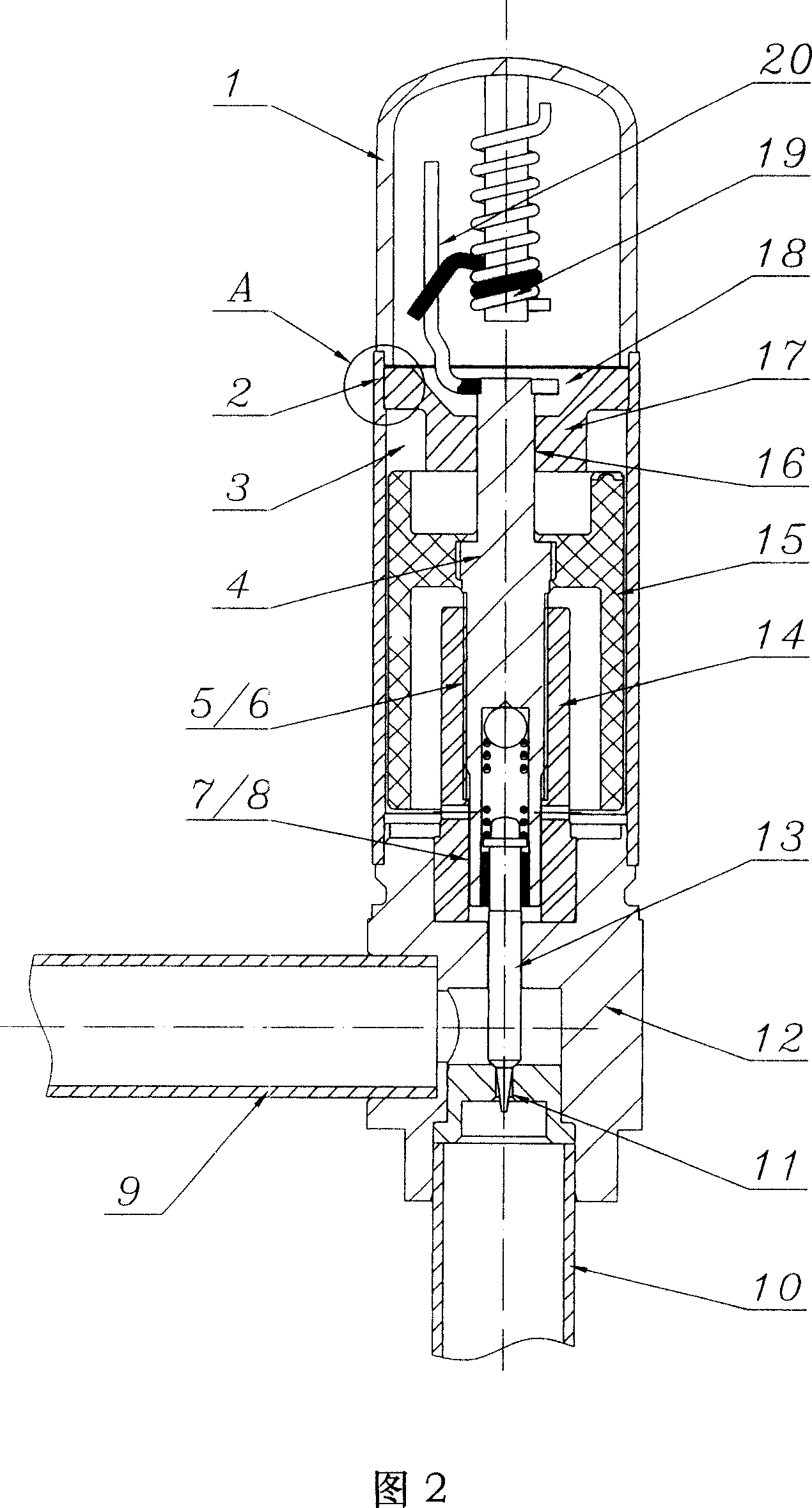
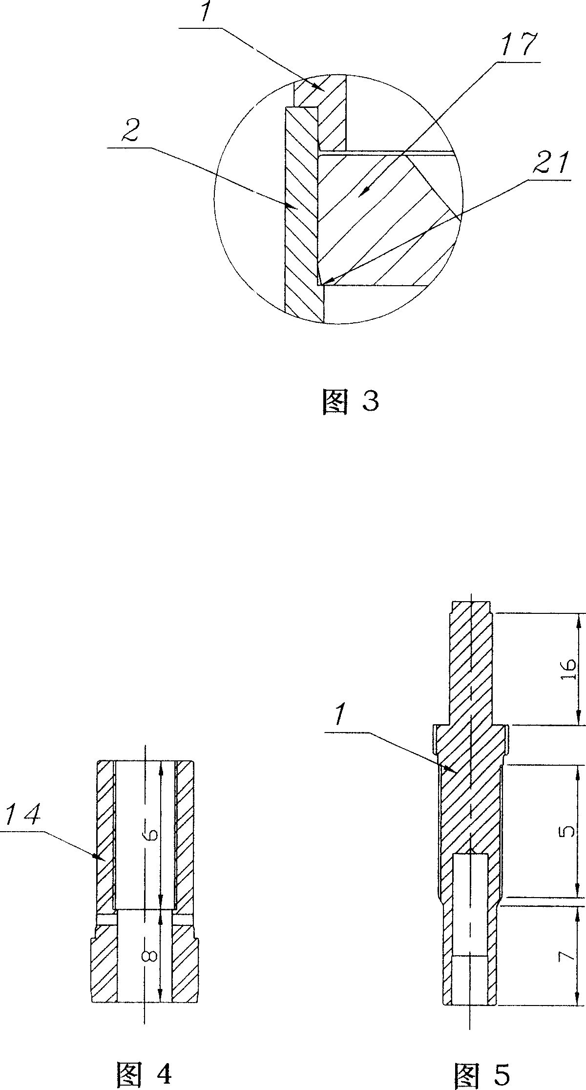
[0021] As for the electric valve shown in Figure 2, there are a metal stopper 19, a stop rod 20, and a magnet 15 in the housing cavity 3, and the screw rod 4 and the magnet 15 are integrally injection-molded, and the two ends of the screw rod 4 (see Figure 5) are respectively The upper guide section 16 and the lower guide section 7 protruding from the end face of the magnet 15 have an external thread section 5 between the two guide sections of the screw rod 4, wherein the upper guide section 16 is located in the center hole of the guide member 17 and is in a clearance fit. The lower guide section 7 is located in the lower guide section 8 of the nut 14 and also has a clearance fit, and the guide piece is mounted on the inner wall of the housing 2 . As a result, the central axis of the magnet 15 coincides with the central axes of the valve body 12 and the housing 2 as much as possible so as to reduce the vibration of the magnet. The external thread section 5 cooperates with the ...


PUM


Abstract

This invention is a motorized valve that is used to adjust refrigerant quantity of refrigerating system. Guiding element and nut are arranged at upper and lower sides of magnet inside of the holding cavity. The said guiding element has guiding hole. The said nut includes internal screw thread section and lower guiding section. The said lead screw includes intermediate external thread section, upper and lower guiding sections that protrude from upper and lower end faces of magnet. The said external and internal thread sections are cooperated. The said upper guiding section is located in the said guiding hole of guiding element. The said lower guiding section is located in the lower guiding section of the said nut. This invention extends the guiding length of lead screw. It can reduce the swing range of lead screw. This invention decreases magnet vibration and increases the abrasion resistant capability of thread section.

Description

technical field [0001] The invention relates to components used in refrigeration systems, in particular to an electric valve for regulating refrigerant flow. Background technique [0002] A common electric valve at present is shown in FIG. 1 , which includes a valve body 12 and a coil (not shown) sleeved on the valve body 12 . A metal stopper 19, a stop rod 20, and a magnet 15 are arranged in the accommodation chamber 3, and the screw mandrel 4 and the magnet 15 are integrally injection-molded. The nut 14 has a guide section 23 (position corresponding to the screw mandrel guide section 22), an internal thread section 6, and the stop rod 20 is connected with the screw mandrel 4. The internal thread section 6 on the nut 14 cooperates with the external thread section 5 on the screw rod 4 so that the circular motion of the magnet 15 in response to the electromagnetic field of the coil is converted into the linear motion of the valve needle 13, so that the valve needle 13 moves ...

Claims


Application Information

Patent Timeline
Patent Type & Authority Applications(China)
IPC IPC(8): F16K1/00F16K31/06F25B41/06
CPCF25B2341/065Y02B30/72Y02B30/70F25B41/34
Inventor 张胜昌詹才意
Owner ZHEJIANG SANHUA CLIMATE & APPLIANCE CONTROLS GRP CO LTD
Why Eureka
Try Eureka