
Travel driving apparatus of vehicle

A technology for driving equipment and vehicles, which is used in the control of driving, vehicle energy storage, vehicle components, etc.

Active Publication Date: 2017-10-20
MITSUBISHI MOTORS CORP
View PDF7 Cites 4 Cited by
  • Summary
  • Abstract
  • Description
  • Claims
  • Application Information

AI Technical Summary

Problems solved by technology

Therefore, in a vehicle driven to travel in the continuous mode by the rear motor supplied with part of the electric power generated by the generator as described above and stepped down by the transformer, there is a possibility that when the vehicle The electric power input from the generator to the transformer exceeds the upper limit value when the traveling drive torque increases

Method used


Image

  • Travel driving apparatus of vehicle
  • Travel driving apparatus of vehicle
  • Travel driving apparatus of vehicle

Examples


Embodiment Construction

[0018] Hereinafter, embodiments of the present invention will be described with reference to the accompanying drawings.

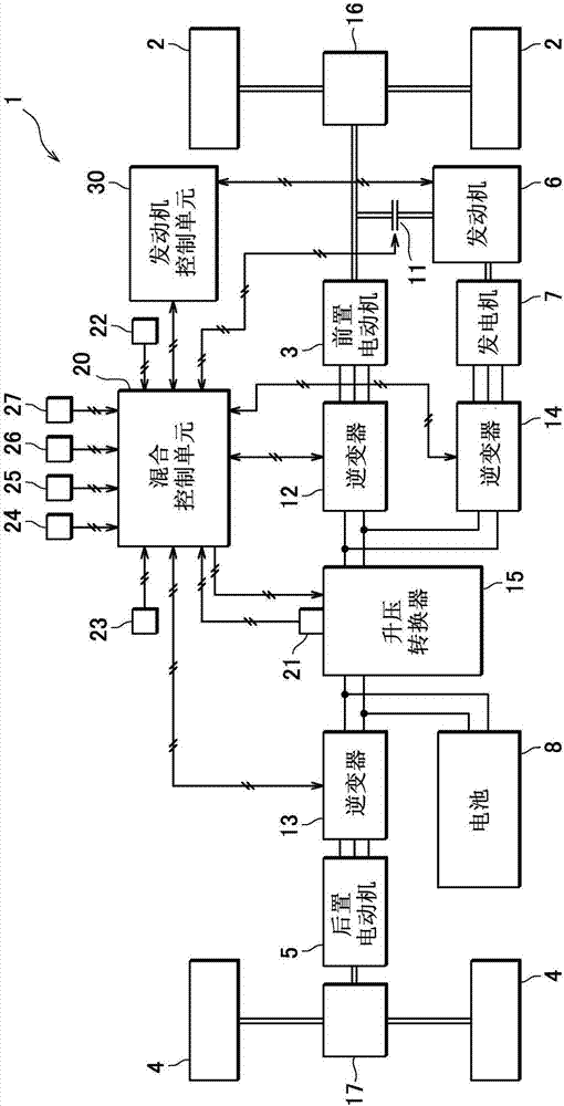
[0019] figure 1 is a schematic configuration diagram of a travel drive device 1 for a vehicle according to one embodiment of the present invention.

[0020] Such as figure 1 As shown in , a vehicle equipped with a travel drive apparatus 1 according to an embodiment of the present invention is a four-wheel drive hybrid vehicle provided with an electrically driven front motor 3 for driving the front wheels 2 (first travel drive wheels) (first electric motor), electrically driven rear electric motor 5 (second electric motor) for driving rear wheels 4 (second traveling drive wheels), engine 6 (internal combustion engine), generator 7 , and battery 8 .

[0021] Engine 6 may drive front wheels 2 via front transaxle 16 and drive generator 7 to generate electricity. Furthermore, the engine 6 is connected to the front wheels 2 so that electric power can be transm...


PUM


Abstract

In a hybrid vehicle including a front motor (3) for driving front wheels, a rear motor (5) for driving rear wheels, a generator (7) for generating power by being driven by an internal combustion engine, and a step-up converter (15) for stepping up the voltage from a battery (8) and supplying power to the front motor (3), while stepping-down the generated power of the generator (7) and supplying the power to the rear motor (5), a hybrid control unit (20) decreases the power supplied from the generator (7) to the rear motor (5), and increases the power supplied from the battery (8) to the rear motor (5) when input power of the step-up converter (15) is limited based on a temperature condition of the step-up converter (15).

Description

technical field [0001] The invention relates to the control of the traveling drive of a vehicle. Background technique [0002] Among the hybrid vehicles that have been developed recently, there is known a vehicle in which the vehicle is operable in a running mode in which it is driven by an electric motor while electric power is generated by a generator driven by an internal combustion engine (continuous mode). for driving wheels. [0003] In addition, there has also been proposed a vehicle including a transformer for boosting a voltage in which a voltage output from an on-vehicle battery is boosted by the transformer to drive a motor. [0004] For example, Japanese Patent Laid-Open No. 2007-325352 discloses a vehicle including an electrically driven front motor for driving front wheels and an electric rear motor for driving rear wheels. In the vehicle disclosed in Patent Document 1, the front motor is driven by a voltage output from an on-vehicle battery and boosted by an...

Claims


Application Information

Patent Timeline
Patent Type & Authority Applications(China)
IPC IPC(8): B60K6/26B60K6/40B60K6/52B60W20/10B60W10/06B60W10/08B60W10/26B60L50/15
CPCB60K6/26B60K6/40B60K6/52B60W10/06B60W10/08B60W10/26B60W20/10B60W2520/105B60W2520/125B60W2540/18B60W2710/06B60W2710/083B60W2710/242B60K1/00B60K6/442B60K6/448B60K17/354B60K17/356B60K2001/001B60L15/007B60L50/61B60L2210/14B60L2240/525B60L2260/28B60W10/02B60W20/50B60W50/029B60W50/038B60W2050/0295B60W2710/086B60W2720/403B60K1/02Y02T10/62Y02T10/64Y02T10/70Y02T10/72Y10S903/906Y10S903/916Y02T10/7072
Inventor 清水亮生驹宪彦蒲地诚安部洋则宫本直树
Owner MITSUBISHI MOTORS CORP
Learn More