
Nuclear power plant earthquake monitoring method, device and system

A technology for earthquake monitoring and nuclear power plants, applied in the field of nuclear power plants, can solve problems such as human error in operation, shutdown of nuclear power plants, and irrationality

Active Publication Date: 2017-10-20
中广核工程有限公司 +2
View PDF2 Cites 5 Cited by
  • Summary
  • Abstract
  • Description
  • Claims
  • Application Information

AI Technical Summary

Problems solved by technology

[0006] It may cause false alarms of non-destructive earthquakes such as local earthquakes and small earthquakes, because even if the peak acceleration of the earthquake motion is relatively large, if the high-frequency components of the earthquake motion are rich, the energy of the earthquake motion may be relatively low instead, which has no effect on the operation of the nuclear power plant. no damaging effects
Therefore, it is unreasonable to use Peak Ground Acceleration (PGA) as the parameter for judging whether a nuclear power plant needs to be shut down by the current nuclear power plant seismic monitoring device, which may cause the operator to trigger the shutdown protection device and cause unnecessary shutdown of the nuclear power plant. cause economic loss
[0007] Secondly, the current seismic monitoring device used in nuclear power projects only sends an alarm to the operator after an earthquake is detected, and the operator decides whether to manually shut down the reactor after checking the seismic data
This not only increases the workload of the operator, but also risks human error

Method used


Image

  • Nuclear power plant earthquake monitoring method, device and system
  • Nuclear power plant earthquake monitoring method, device and system
  • Nuclear power plant earthquake monitoring method, device and system

Examples


Embodiment Construction

[0044] In order to make the purpose of the invention, technical solution and beneficial technical effects of the present invention clearer, the present invention will be further described in detail below in conjunction with the accompanying drawings and specific implementation methods. It should be understood that the specific implementations described in this specification are only for explaining the present invention, not for limiting the present invention.

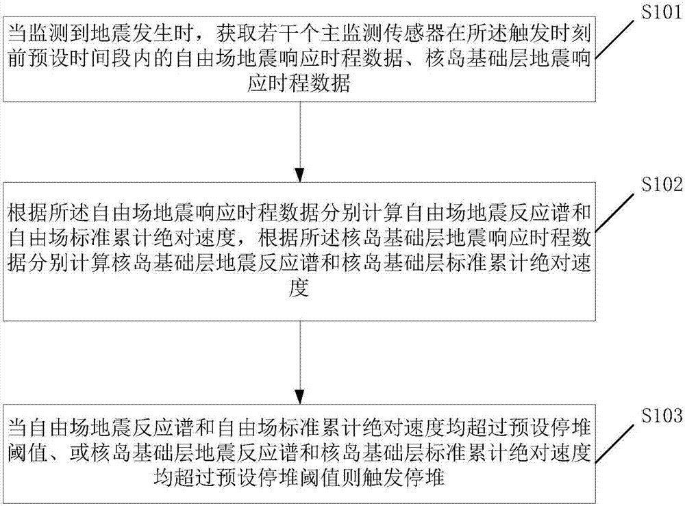
[0045] see figure 1 , a work flow chart of a nuclear power plant earthquake monitoring method in the present invention, including: step S101, when an earthquake is detected, obtain the free-field seismic response time of several main monitoring sensors within a preset time period before the triggering moment Earthquake data, nuclear island base layer seismic response time history data;

[0046] Step S102: Calculate the free-field seismic response spectrum and the free-field standard cumulative absolute velocity accordi...


PUM


Abstract

The invention discloses a nuclear power plant earthquake monitoring method, device and system. The earthquake monitoring method comprises the steps of when occurrence of an earthquake is monitored, acquiring free field earthquake response time-displacement data and nuclear island foundation layer earthquake response time-displacement data of a plurality of main monitoring sensors within a preset time period before a triggering moment; respectively calculating a free field earthquake response spectrum and free field standard cumulative absolute velocity, and respectively calculating a nuclear island foundation layer earthquake response spectrum and nuclear island foundation layer standard cumulative absolute velocity; and triggering shutdown when both the free field earthquake response spectrum and the free field standard cumulative absolute velocity exceed a preset shutdown threshold or both the nuclear island foundation layer earthquake response spectrum and the unclear island foundation layer standard cumulative absolute velocity exceed the preset shutdown threshold. Compared with the prior art, the earthquake reaction spectrum and the standard cumulative absolute velocity are adopted to act as parameters of earthquake impact assessment, the influence and intensity of earthquake motions can be evaluated stably and accurately, and false triggering is avoided.

Description

technical field [0001] The invention belongs to the technical field of nuclear power plants, and more specifically, the invention relates to a nuclear power plant earthquake monitoring method, device and system. Background technique [0002] According to the relevant requirements of GB50267-97 "Code for Seismic Design of Nuclear Power Plants" and NB / T20076-2012 "Code for Seismic Instrumentation of Nuclear Power Plants", nuclear power plants must design seismic monitoring devices to evaluate possible earthquakes during the operation of nuclear power plants, so as to effectively control The influence of earthquake motion on the safety of nuclear power plant operation. The seismic monitoring device monitors the ground motion by arranging multiple seismic signal sensors in the free field of the entire nuclear power plant site and typical representative locations of the plant structures, and after a series of algorithm analysis, the results are sent to the main control room for t...

Claims


Application Information

Patent Timeline
IPC IPC(8): G01V1/00
CPCG01V1/01
Inventor 惠志光陈冬雷袁超吕建平江辉何大宇刘东波史觊张瑜张旺盛
Owner 中广核工程有限公司
Learn More