Single-needle electronic pulse ignition induction circuit

An electronic pulse and induction circuit technology, which is applied to circuits, circuits, and spark gaps dedicated to spark gaps, can solve problems such as limited service life of gas discharge tubes, drop in initial discharge voltage, and unreliable trigger methods, and achieve manufacturing Low cost, low on-resistance, and the effect of eliminating false triggering

Active Publication Date: 2010-12-15
GUANGDONG HUAMEI JUNDA ELECTRIC APPLIANCES
View PDF4 Cites 15 Cited by
  • Summary
  • Abstract
  • Description
  • Claims
  • Application Information

AI Technical Summary

Problems solved by technology

But its disadvantage is: the gas discharge tube produces ionization loss to the inert gas inside when it discharges, and the service life of the entire gas discharge tube is limited due to the limited inert gas
The discharge life of a general gas discharge tube is about 1 million times, and after a period of use, the initial discharge voltage parameter of the discharge tube drifts, and the final failure mode is that the initial discharge voltage drops and eventually short-circuits, resulting in unstable circuit operation after a period of use , the trigger method is unreliable

Method used


Image

  • Single-needle electronic pulse ignition induction circuit
  • Single-needle electronic pulse ignition induction circuit

Examples


Embodiment Construction

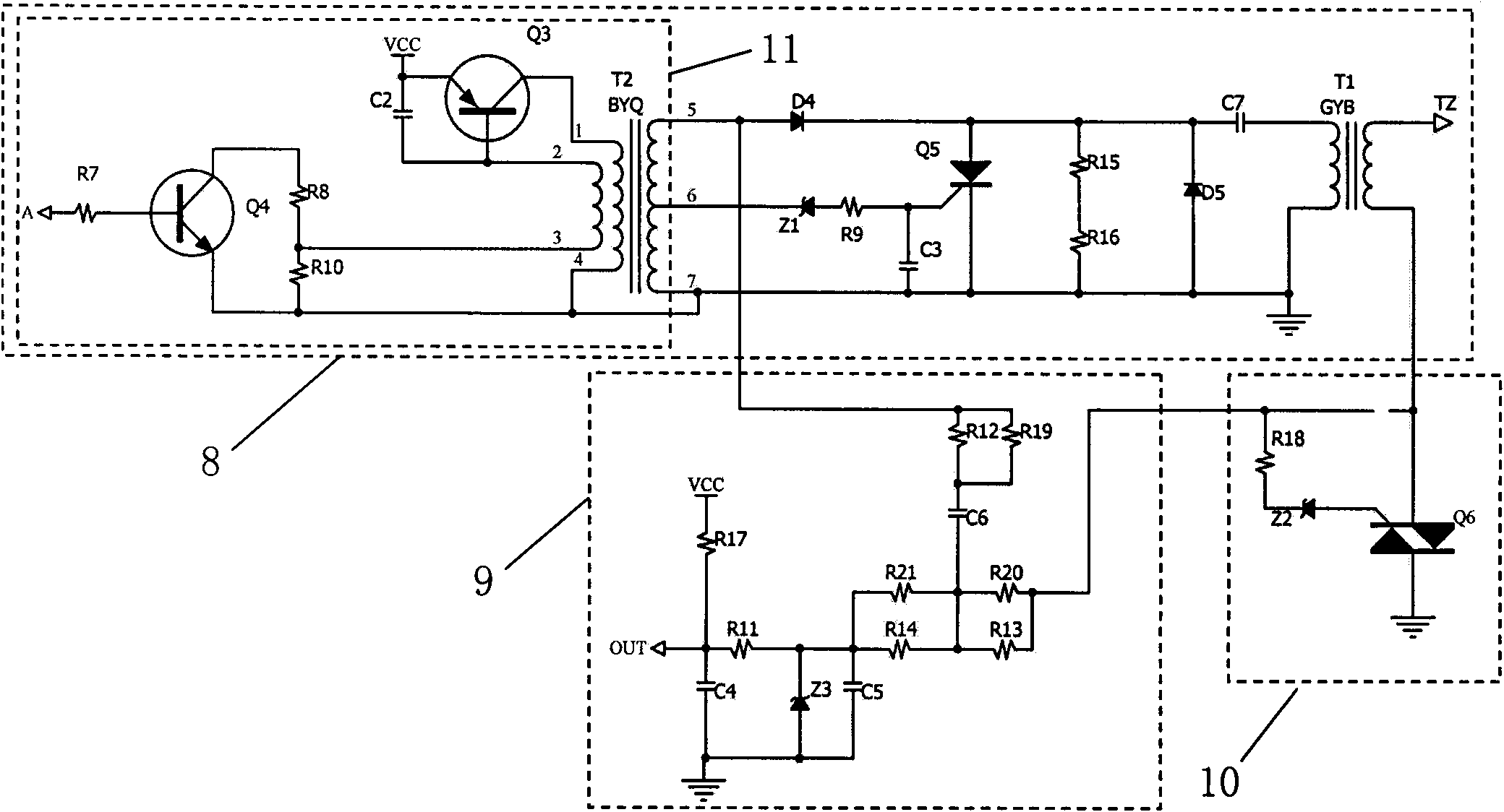
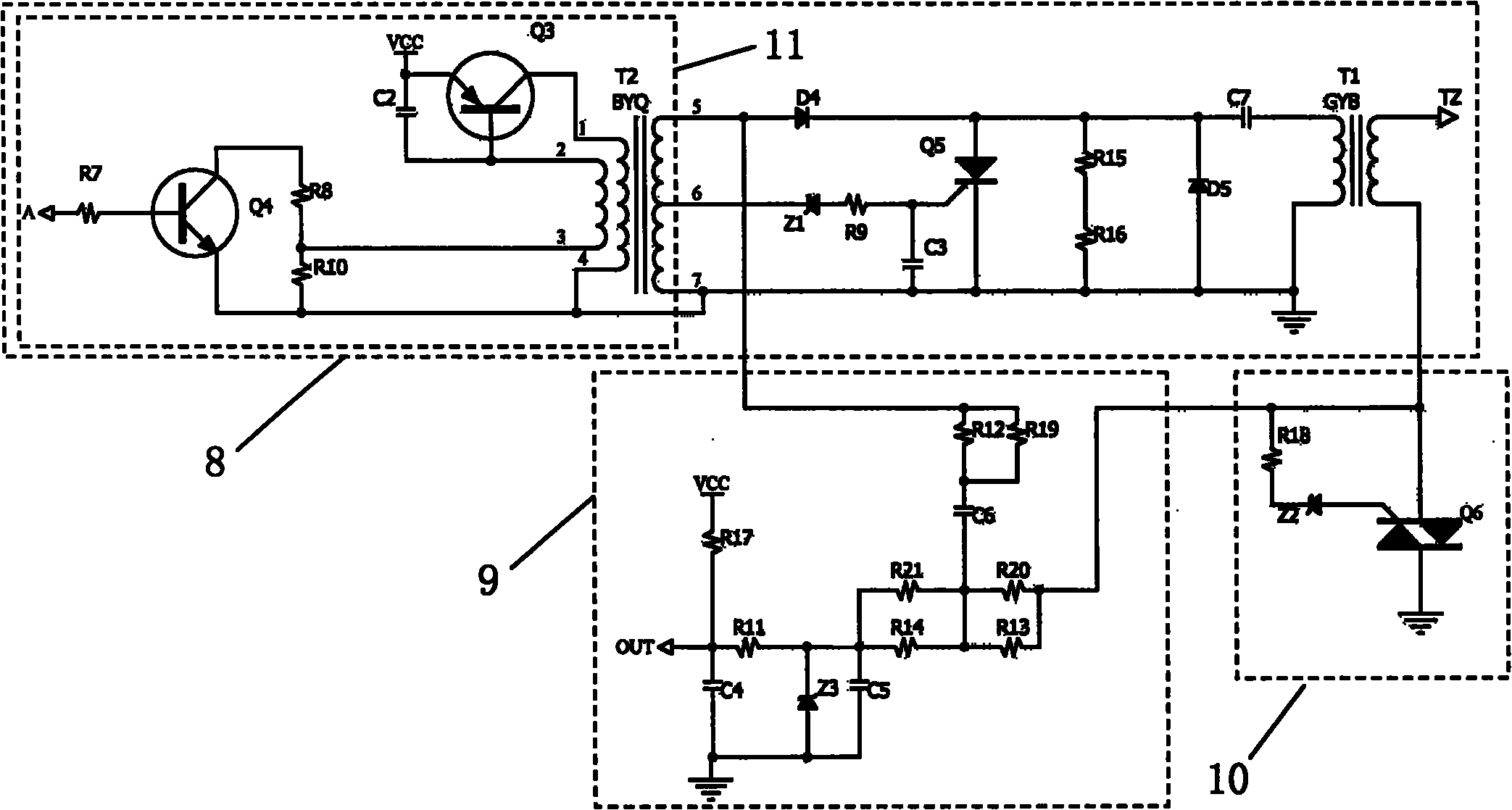
[0021] Such as figure 1 A single-needle electronic pulse ignition induction circuit shown includes an energy storage trigger ignition circuit 8 and a flame ion detection circuit 9, and the energy storage trigger ignition circuit 1 also includes a boost oscillating circuit 11, and the boost oscillating circuit 11 Including triode Q3 and triode Q4, the emitter of triode Q3 is connected to the AC voltage Vcc input, the collector is connected to port 1 of the first primary of a transformer T2, and the base is respectively connected to the anodes of the shunt resistors R8 and R10 through the second primary end of the transformer T2. The cathode of the shunt resistor R8 is connected to the collector of the transistor Q4, the emitter of the transistor Q4 is connected to the cathode of the shunt resistor R10 to ground, and a control input terminal A is connected to the base of the transistor Q4; the first primary 4 terminals of the transformer T4 are grounded. The energy storage trigg...


PUM


Abstract

The invention relates to an electronic pulse ignition induction circuit for civil and commercial fuel heat type gas appliances, in particular to a single-needle electronic pulse ignition induction circuit. The single-needle electronic pulse ignition induction circuit comprises a stored energy trigger ignition circuit and a flame ion detection circuit, wherein the stored energy trigger ignition circuit comprises a transformer and an ignition coil; one end of the flame ion detection circuit is connected with a secondary first end of the transformer and the other end of the flame ion detection circuit is connected with a secondary second end of the ignition coil; and a probe is connected with a secondary first end of the ignition coil. The single-needle electronic pulse ignition induction circuit also comprises a function switching circuit which comprises the first controlled silicon which is connected between the secondary second end of the ignition coil and the ground. The single-needle electronic pulse ignition induction circuit has the advantages of simple structure, long service life, accurate trigger and low production cost.

Description

Technical field: [0001] The invention relates to an electronic pulse ignition circuit for civilian and commercial heating gas appliances, in particular to a single-needle electronic pulse ignition induction circuit. Background technique: [0002] In the past, the flame detection schemes of electronic pulse igniters on the market can be divided into two categories. One type uses thermocouple method, which uses thermoelectric effect to analyze the size of thermoelectric potential, so as to reflect the temperature on the working end of thermocouple to judge whether there is flame burning; the other The class uses ion flame detection, which utilizes the one-way conduction characteristic of the flame. When there is a flame, the loads in the positive and negative half-cycle detection circuits are different, and the flame can be judged by measuring the integral voltage as negative. [0003] However, during the ignition process, the secondary of the transformer must be grounded to p...

Claims


Application Information

Patent Timeline
Patent Type & Authority Applications(China)
IPC IPC(8): H01T15/00
Inventor 张剑明王岂难
Owner GUANGDONG HUAMEI JUNDA ELECTRIC APPLIANCES
Why Eureka
Try Eureka