Imaging method, imaging device and computer storage medium

An imaging method and medium technology, applied in the field of seismic exploration, can solve problems such as poor imaging quality

Active Publication Date: 2017-10-20
INST OF GEOLOGY & GEOPHYSICS CHINESE ACAD OF SCI
View PDF5 Cites 10 Cited by
  • Summary
  • Abstract
  • Description
  • Claims
  • Application Information

AI Technical Summary

Problems solved by technology

[0008] The object of the present invention is to provide an imaging method, imaging device

Method used


Image

  • Imaging method, imaging device and computer storage medium
  • Imaging method, imaging device and computer storage medium
  • Imaging method, imaging device and computer storage medium

Examples


Embodiment 1

[0249] refer to Figure 10(a) to Figure 11(c) As shown, in order to verify the imaging quality of the imaging method of this application, the experimenters used this method to image on the marmousi2 model and the salt dome model. Referring specifically to Figure 10(a) and Figure 10(b), Figure 10(a) and Figure 10(b) are the local results of PP imaging and PS imaging on the marmousi2 model. Among them, PP represents the longitudinal wave at the shot point and the longitudinal wave at the receiver point. PS represents the longitudinal wave at the shot point and the shear wave at the receiver point.

[0250] Figure 11(a) to (c) are the PP imaging results of this method on the Marmousi2 model; the PP imaging results on the salt dome model and the PS imaging results on the salt dome model. where PP represents the longitudinal wave at the shot point and the longitudinal wave at the receiver point. PS represents the longitudinal wave at the shot point and the shear wave at the rece...


PUM


Abstract

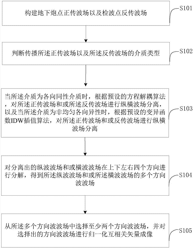
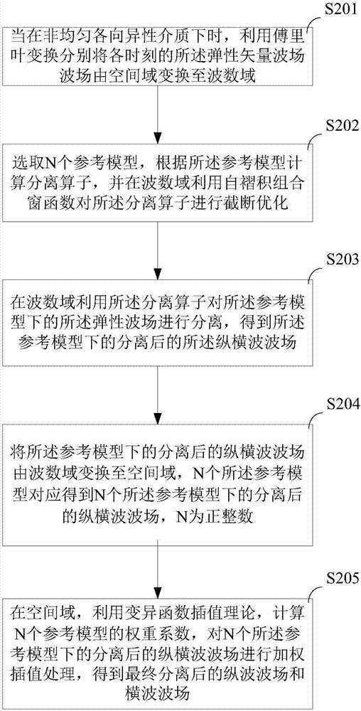
The application discloses an imaging method, an imaging device and a computer storage medium. The method includes the steps of constructing an underground shot point forward propagation wave field and a detection point back propagation wave field; determining types of media in which the forward propagation wave field and the back propagation wave field are propagated; when the media are isotropic, subjecting the forward propagation wave field and the back propagation wave field to longitudinal and transverse wave field separation according to a preset equation decoupling algorithm, and when the media are heterogeneous anisotropic, subjecting the forward propagation wave field and the back propagation wave field to longitudinal and transverse wave field separation according to a preset variation function IDW interpolation algorithm; decomposing the separated longitudinal wave field and/or transverse wave field in the four directions of the up and down and left and right to obtain a plurality of directional wave fields of the longitudinal wave field and/or transverse wave field; and selecting at least two directional wave fields from the plurality of directional wave fields, and subjecting the selected wave fields to normalized cross-correlation vector imaging. The imaging method can effectively suppress the coupling noise, low frequency noise and imaging artifact noise generated during the inverse time migration of elastic waves and improve the image quality.

Description

technical field [0001] The present application relates to the field of seismic exploration, in particular to an imaging method, an imaging device and a computer storage medium. Background technique [0002] The elastic wave seismic exploration technology has the advantages of high accuracy of medium parameter calculation, high certainty of medium parameter inversion, high imaging accuracy, high reservoir prediction accuracy and high fluid identification accuracy. Because the elastic wave equation contains more information, it can describe the composition of the Earth's medium more accurately than the acoustic wave equation. Therefore, it is very important to study elastic wave reverse time prestack depth migration technology to improve the quality of seismic imaging and solve some new problems in seismic exploration. [0003] Among them, the coupling noise, low-frequency noise and imaging artifact noise of elastic wave imaging results have become the focus and difficulty of...

Claims


Application Information

Patent Timeline
IPC IPC(8): G01V1/28
CPCG01V1/28
Inventor 王之洋胡婷袁雨欣刘洪
Owner INST OF GEOLOGY & GEOPHYSICS CHINESE ACAD OF SCI
Why Eureka
Try Eureka