
Anti-derailing device of bridge-crane trolley walking mechanism

A technology of bridge crane and traveling mechanism, which is applied in the direction of traveling mechanism, track system, transportation and packaging, etc. It can solve problems such as endangering the personal safety of operators, damage to transported items, and derailment of cranes, so as to improve production efficiency and facilitate installation and disassembly, prevent derailment effect

Inactive Publication Date: 2017-10-24
ANHU WUHU CHANGJIANG JACK UP EQUIP CO LTD
View PDF7 Cites 0 Cited by
  • Summary
  • Abstract
  • Description
  • Claims
  • Application Information

AI Technical Summary

Problems solved by technology

[0002] At present, during the operation of the bridge crane, because the wheel rim on the operating mechanism of the crane is very shallow, if the running motor on one side suddenly gets stuck and fails during driving, the motor on the other side is still running. If the running mechanism is not synchronized, there will be a large torsion force. This torsion force will act on the end beam, causing the end beam to twist. It will cause vicious events such as derailment and falling of the crane, which will not only endanger the personal safety of the operator, but also cause damage to the transported items and cause unnecessary economic losses. In view of this problem, it is necessary to design a bridge type The anti-derailment device of the traveling mechanism of the crane trolley to effectively avoid the occurrence of derailment of the crane

Method used


Image

  • Anti-derailing device of bridge-crane trolley walking mechanism
  • Anti-derailing device of bridge-crane trolley walking mechanism
  • Anti-derailing device of bridge-crane trolley walking mechanism

Examples


Embodiment

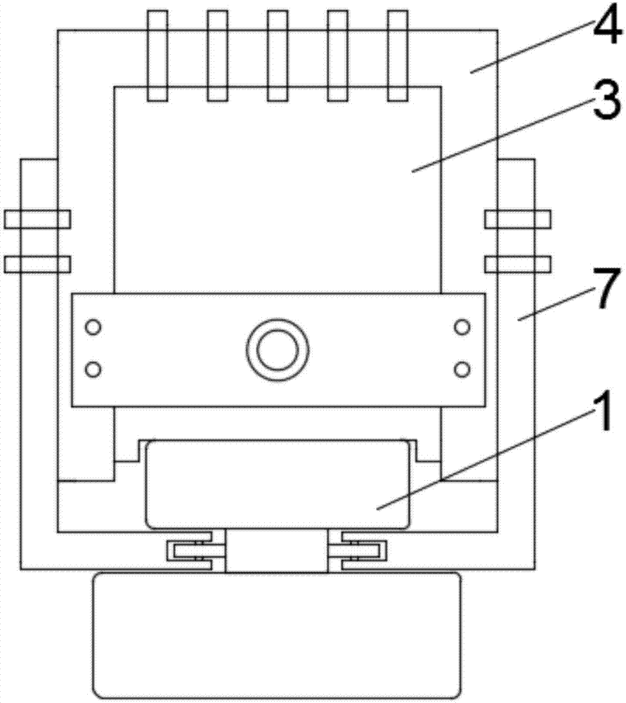
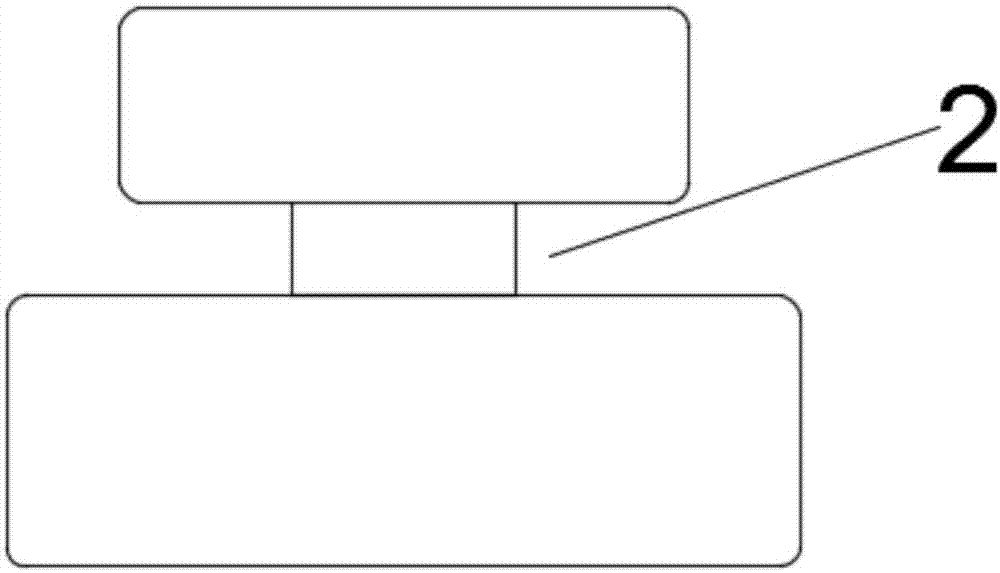
[0024] Such as figure 1 with figure 2 As shown, the present invention provides an anti-derailment device for the trolley traveling mechanism of a bridge crane, comprising an I-shaped slide rail 1, and the sides of the I-shaped slide rail 1 are symmetrically provided with track grooves 2, and the I-shaped slide rail 1 There is a trolley sliding block 3 on the top, and the crane trolley runs longitudinally along the track on the I-shaped slide rail 1, and moves the items that need to be moved to the designated position;

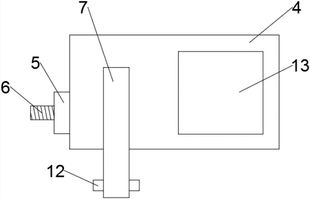
[0025] Such as Figure 1 to Figure 3 As shown, a bracket 4 is fixedly installed on the sliding block 3 of the trolley, and the bracket 4 is connected and fixed on the sliding block 3 of the trolley through bolts and nuts. The bracket 4 has a concave structure, so that the bracket 4 is fixed on the sliding block 3 of the trolley. On the other hand, it is not easy to deform when subjected to force in the left and right directions, preventing the bracket 4 from...


PUM


Abstract

The invention discloses an anti-derailment device for a trolley traveling mechanism of an overhead crane, comprising an I-shaped slide rail, a track groove is symmetrically arranged on the side of the I-shaped slide rail, and a trolley sliding block is arranged on the I-shaped slide rail. A bracket is fixedly installed on the trolley sliding block, the bracket has a concave structure, the upper end of the bracket is fixed on the upper surface of the trolley sliding block, the front end of the bracket is provided with a buffer plate, and the buffer plate is provided with a buffer plate At the meeting, limiters are fixedly installed on both sides of the bracket, the limiters are L-shaped, and the limiters are composed of a limiter arm in the vertical direction and a limiter rod in the horizontal direction. One end of the position rod is provided with a groove, the groove is provided with a rotating shaft, a sliding wheel is fixedly installed on the rotating shaft through a bearing, and the sliding wheel is arranged in the track groove, the invention effectively prevents the running machine on the crane. The rail derailment can avoid the occurrence of accidents, and has the advantages of simple structure and easy installation and disassembly.

Description

technical field [0001] The invention relates to the technical field of hoisting equipment, in particular to an anti-derailment device for a trolley traveling mechanism of a bridge crane. Background technique [0002] At present, during the operation of the bridge crane, because the wheel rim on the operating mechanism of the crane is very shallow, if the running motor on one side suddenly gets stuck and fails during driving, the motor on the other side is still running. If the running mechanism is not synchronized, there will be a large torsion force. This torsion force will act on the end beam, causing the end beam to twist. It will cause vicious events such as derailment and falling of the crane, which will not only endanger the personal safety of the operator, but also cause damage to the transported items and cause unnecessary economic losses. In view of this problem, it is necessary to design a bridge type The anti-derailment device of the traveling mechanism of the cr...

Claims


Application Information

Patent Timeline
Patent Type & Authority Applications(China)
IPC IPC(8): B66C7/16B66C9/18
CPCB66C7/16B66C9/18
Inventor 焦来文
Owner ANHU WUHU CHANGJIANG JACK UP EQUIP CO LTD
Learn More