Card box capable of preventing dropping of cards and card issuing device applying the card box

A card issuing device and card box technology, which is applied in the direction of instruments, computer parts, transmission record carriers, etc., can solve the problems of smart card dropping, affecting production operations, smart card loss, etc., and achieve the effect of avoiding loss

Active Publication Date: 2017-10-24
GUANGZHOU MINGSEN TECH CO LTD
View PDF12 Cites 2 Cited by
  • Summary
  • Abstract
  • Description
  • Claims
  • Application Information

AI Technical Summary

Problems solved by technology

When the operator carries the card box and installs the card box in the self-service card removal machine, if the card box tilts or vibrates and other accidents occur, the smart card st

Method used


Image

  • Card box capable of preventing dropping of cards and card issuing device applying the card box
  • Card box capable of preventing dropping of cards and card issuing device applying the card box
  • Card box capable of preventing dropping of cards and card issuing device applying the card box

Examples


Embodiment 1

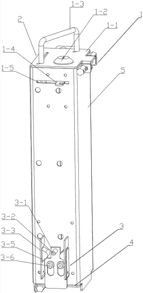
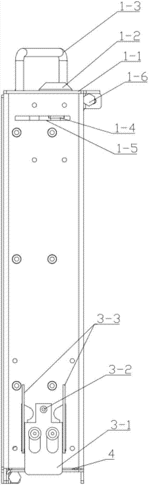
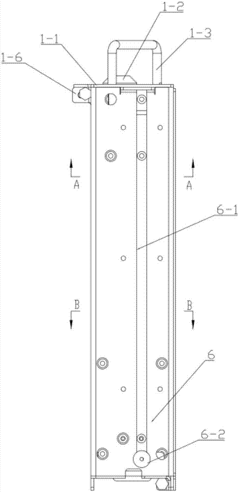
[0036] see Figure 1-Figure 6 , the card box a of the present invention that can prevent the card from falling includes a box body 5, a lateral card-out opening 4 arranged at the lower end of the box body 5, and a card-out blocking mechanism 3 arranged on the card-out opening 4, wherein, The card ejection blocking mechanism 3 includes a card ejection baffle 3-1 and a card ejection block assembly that drives the card ejection baffle 3-1 to move to open or close the card outlet 4, wherein the card ejection The blocking assembly includes two first support plates 3-3 arranged on both sides of the card output baffle 3-1 and perpendicular to the card output baffle 3-1, and two first support plates 3-3 arranged on each side The elastic block 3-5, wherein, the first support plate 3-3 on both sides is installed on the box body 5, the lower end of the elastic block 3-5 is fixed on the first support plate 3-3, and the upper end is a free end, the upper end of the elastic block 3-5 is pr...

Embodiment 2

[0053] see Figure 11 The difference between this embodiment and Embodiment 1 is that the elastic stop 3-5 is provided with an inclined surface 3-11 inclined outward in a direction away from the elastic stop 3-5, and one end of the inclined surface 3-11 is connected to The arc-shaped protrusion 3-8 is connected, and the other end is connected with the locking surface 3-9. In the process of the card box a leaving the card issuing device b, after the force exerted on the support column 3-2 disappears, the card ejection baffle plate 3-1 moves downward due to its own gravity. , the elastic stoppers 3-5 on both sides move toward each other in order to return to their original shape. When the arc-shaped guide surface 7-7 is located below the locking surface 3-9, the elastic stoppers 3-5 5 is restored to its original shape, so that the card output baffle 3-1 is pressed against the card output port 4, thereby closing the card output port 4. During this process, if the elastic stoppe...


PUM


Abstract

The invention discloses a card box capable of preventing dropping of cards and a card issuing device applying the card box. The card box comprises a box body, a card outlet arranged on a side direction of a lower end of a box body and a card issuing card blocking mechanism arranged on the card outlet. The card issuing card blocking mechanism comprises a card issuing baffle plate and a card issuing card blocking component which drives the card issuing baffle plate to move so that the card outlet is opened or closed. Intelligent cards stored in the card box do not drop out from the card outlet of the card box even if an unexpected situation, such as inclination or vibration and the like, occurs during transportation or installation of the card box to an intelligent card device so that losses of the intelligent cards are avoided and normal production operation is not influenced. The card issuing device comprises a rack, the card box arranged on the rack and a card stirring mechanism which sends out the intelligent cards in the card box. By using the card issuing device, the card outlet of the card box installed on the card issuing device can be automatically opened and card issuing work is completed.

Description

technical field [0001] The invention relates to a smart card device, in particular to a card box and a card issuing device. Background technique [0002] In the production process of smart cards, the processed or unprocessed smart cards are generally stacked in the card box first, and the operator installs the card box storing the smart card in the card issuing device of the smart card device, and the stored in the card through the card issuing device The smart cards in the box are sent out one by one for subsequent further processing. For example, in the self-service card dispenser, the smart cards that have completed all processing are stacked in the card box, and the operator installs the card box on the card issuing device of the self-service card dispenser, and the card issuing device sends the smart card to the smart card delivery device , the user inputs his own information into the self-service card withdrawal machine, and the card withdrawal module in the self-serv...

Claims


Application Information

Patent Timeline
IPC IPC(8): G06K13/14G06K13/08
CPCG06K13/0806G06K13/14
Inventor 王开来李南彪徐飞周逛冷纯镁
Owner GUANGZHOU MINGSEN TECH CO LTD
Why Eureka
Try Eureka