
A multi-angle adjustable solar power generation device

A technology for a power generation device and solar energy, applied in the field of solar power generation, can solve the problems of low regulation efficiency, offset angle of solar panels, poor accuracy, etc., and achieve the effect of improving accuracy and efficiency

Active Publication Date: 2019-04-16
扬州怡华新能源有限公司
View PDF14 Cites 0 Cited by
  • Summary
  • Abstract
  • Description
  • Claims
  • Application Information

AI Technical Summary

Problems solved by technology

[0002] The energy of solar energy comes from the outer celestial bodies of the earth. It is the huge energy released by the fusion of hydrogen nuclei in the sun at ultra-high temperature. Most of the energy needed by human beings comes directly or indirectly from the sun. In recent years, with the development of various energy sources The development of new energy has become a national key project, and solar power generation, as a major project for the development of new energy, is getting closer to our lives. At present, solar power generation mainly uses solar panels to collect sunlight to generate electricity. In order to make power generation more efficient, generally During installation or when the season changes, the angle of the solar panel needs to be adjusted so that it can receive sunlight for a longer time. However, most solar power generation devices currently need to remove the fixing nuts of the solar panel and then adjust the angle of the solar panel. After the adjustment is completed Then tighten the nuts to fix the solar panel. This method of adjusting the angle of the solar panel is not only cumbersome, but the adjustment efficiency is low, and it is easy to cause the angle of the solar panel to shift during the process of tightening the nuts, and the adjustment accuracy is poor.

Method used


Image

  • A multi-angle adjustable solar power generation device
  • A multi-angle adjustable solar power generation device
  • A multi-angle adjustable solar power generation device

Examples


Embodiment Construction

[0017] The following will clearly and completely describe the technical solutions in the embodiments of the present invention with reference to the accompanying drawings in the embodiments of the present invention. Obviously, the described embodiments are only some, not all, embodiments of the present invention.

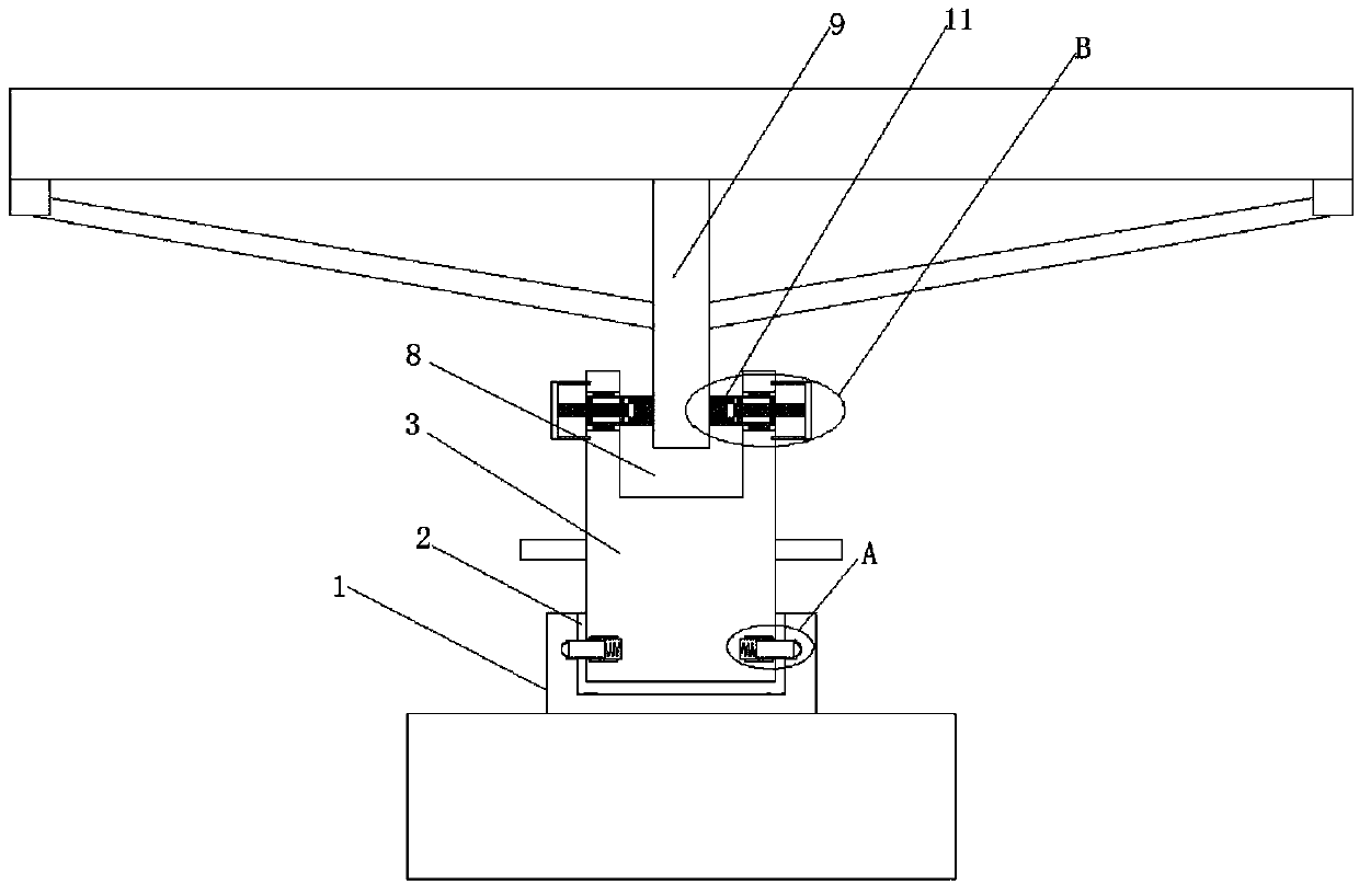
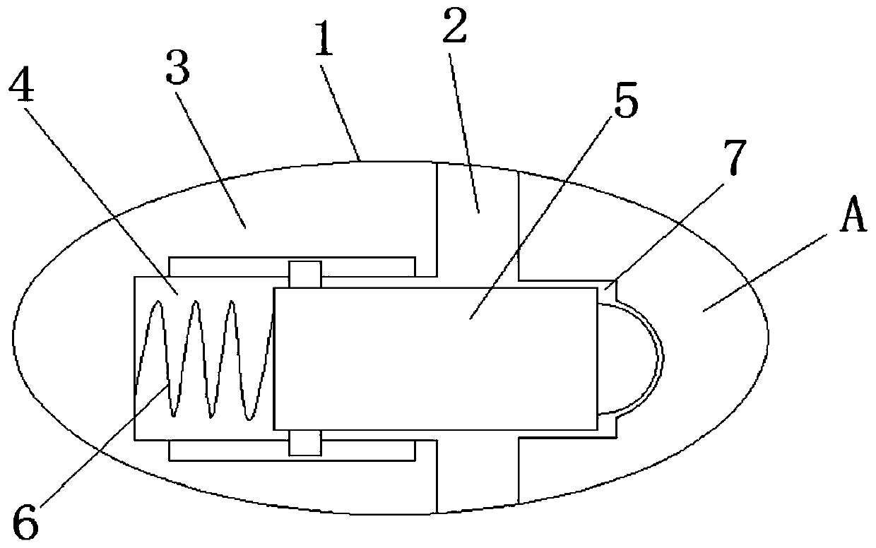
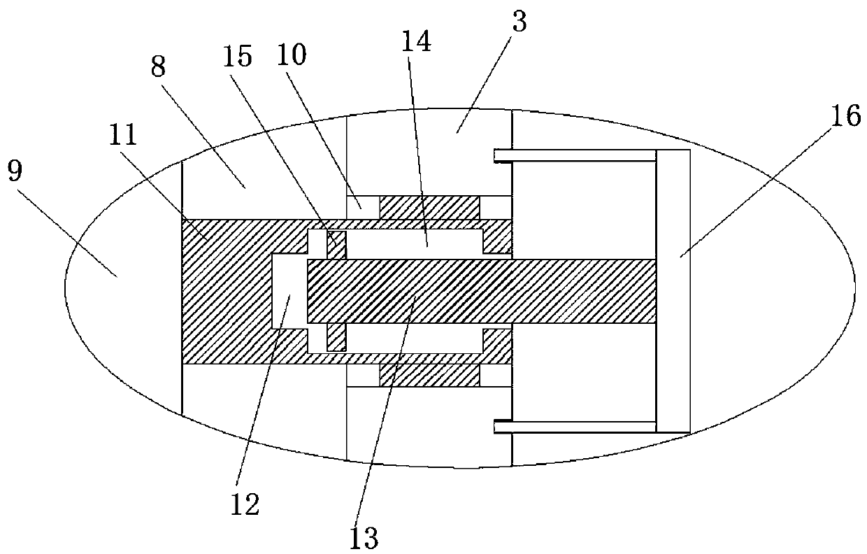
[0018] refer to Figure 1-3 , a multi-angle adjustable solar power generation device, including a fixed seat 1, a first groove 2 is opened on the top of the fixed seat 1, a support column 3 is installed in the first groove 2, and one end of the support column 3 extends To the outside of the first groove 2, four first circular grooves 4 are provided at equal intervals around the periphery of the support column 3, and a sliding rod 5 is slidably installed in the first circular groove 4, and one end of the sliding rod 5 extends to the first circular groove 4, a spring 6 is welded on the inner wall of the first circular groove 4 away from the opening of the first circula...


PUM


Abstract

The invention discloses a solar power generation apparatus with a multi-angle adjustment function. The solar power generation apparatus comprises a fixed base; a first groove is formed in the top of the fixed base; a supporting column is rotationally mounted in the first groove; one end of the supporting column extends to the outside of the first groove; four first circular grooves are formed in the periphery of the supporting column at equal distances; sliding rods are glidingly mounted in the first circular grooves; one ends of the sliding rods extend to the outside of the first circular grooves; a spring is welded on the inner wall on one side, far from the first circular groove opening, of each first circular groove separately; the springs and the corresponding sliding rods are welded and fixed; a sliding groove is formed in the inner wall of the first groove, and the section of the sliding groove is annular; and one ends, positioned outside the four first circular grooves, of the four sliding rods are all glidingly mounted in the sliding groove. By adoption of the solar power generation apparatus, the angles of solar panels in the solar power generation apparatus can be adjusted rapidly and accurately in a multi-angle manner, so that solar panel angle adjusting efficiency by an operator can be improved, and the angle adjustment accuracy is also improved.

Description

technical field [0001] The invention relates to the technical field of solar power generation, in particular to a multi-angle adjustable solar power generation device. Background technique [0002] The energy of solar energy comes from the outer celestial bodies of the earth. It is the huge energy released by the fusion of hydrogen nuclei in the sun at ultra-high temperature. Most of the energy needed by human beings comes directly or indirectly from the sun. In recent years, with the development of various energy sources The development of new energy has become a national key project, and solar power generation, as a major project for the development of new energy, is getting closer to our lives. At present, solar power generation mainly uses solar panels to collect sunlight to generate electricity. In order to make power generation more efficient, generally During installation or when the season changes, the angle of the solar panel needs to be adjusted so that it can rece...

Claims


Application Information

Patent Timeline
Patent Type & Authority Patents(China)
IPC IPC(8): H02S20/32F24S30/00
CPCH02S20/32Y02E10/50
Inventor 朱鸣飞
Owner 扬州怡华新能源有限公司
Learn More