
Brick body angle adjusting device for fly ash brick conveying device

An angle adjustment device and conveying device technology, which is applied in the direction of conveyor objects, transportation and packaging, etc., can solve the problems of reducing the efficiency of fly ash brick angle adjustment, the number of fly ash brick jamming, and damage to the brick angle adjustment device And other problems, to achieve the effect of improving the success rate of drainage, reducing the number of jamming, and good drainage effect

Inactive Publication Date: 2020-04-03
涡阳县晟丰新型建材有限公司
View PDF9 Cites 0 Cited by
  • Summary
  • Abstract
  • Description
  • Claims
  • Application Information

AI Technical Summary

Problems solved by technology

[0007] The object of the present invention is to provide a brick body angle adjustment device for a fly ash brick conveying device, to solve the disorderly placement of bricks on the conveyor belt in the above-mentioned background technology, and the existing fly ash brick conveying device cannot quickly adjust The angle of the bricks is adjusted, so that it is inconvenient for the operator to quickly stack the bricks. The brick body angle adjustment device on the existing fly ash brick conveying device is easy to be stuck by the brick during use, and the brick body angle adjustment device does not have buffering effect, thus easily causing damage to the brick body angle adjustment device, the existing fly ash brick conveying device has a low probability of successful drainage of fly ash bricks, and the number of times of fly ash brick jamming is high, thereby greatly reducing the impact on the fly ash bricks. The problem of the efficiency of fly ash brick angle adjustment

Method used


Image

  • Brick body angle adjusting device for fly ash brick conveying device
  • Brick body angle adjusting device for fly ash brick conveying device
  • Brick body angle adjusting device for fly ash brick conveying device

Examples


Embodiment Construction

[0028] The following will clearly and completely describe the technical solutions in the embodiments of the present invention with reference to the drawings in the embodiments of the present invention.

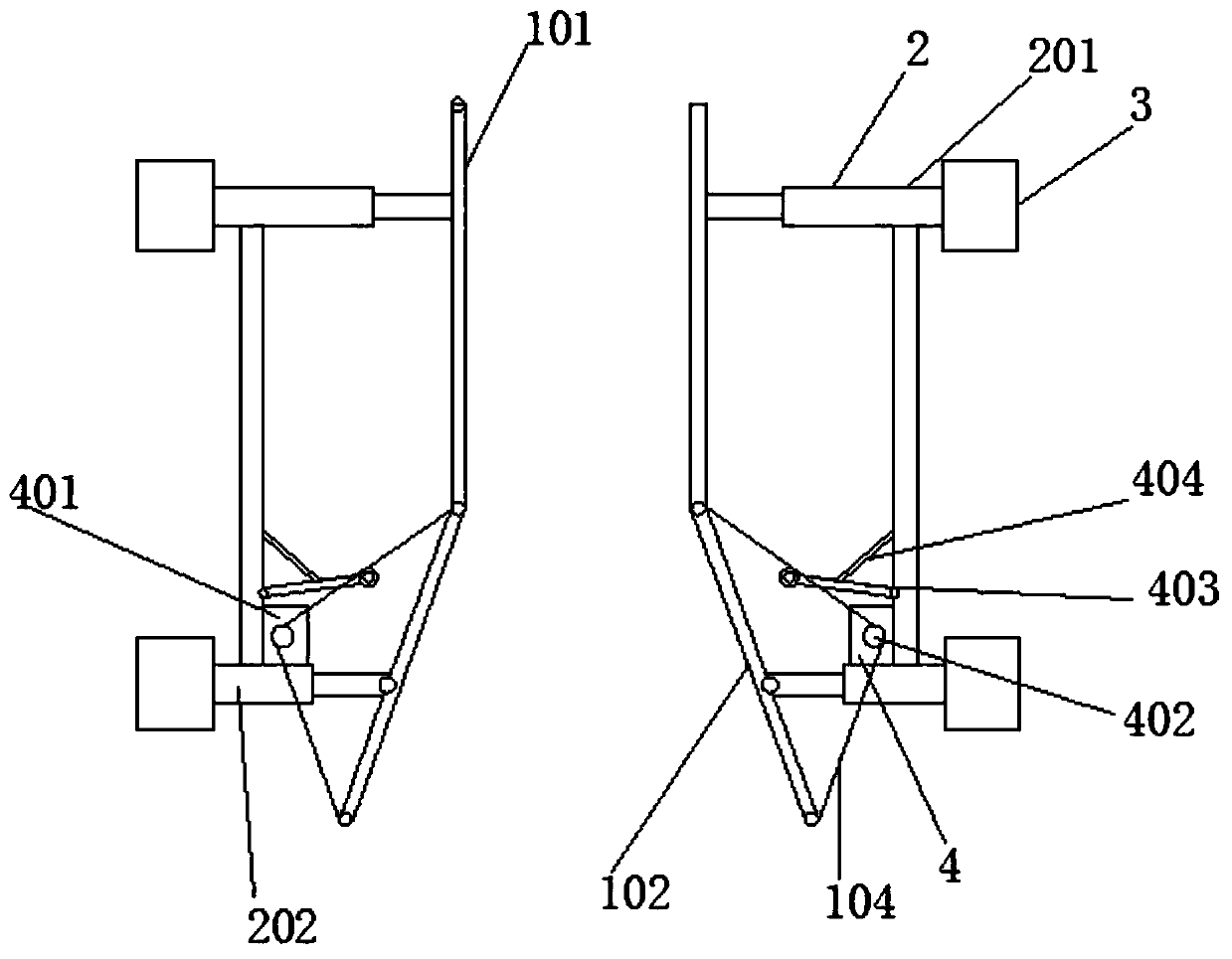
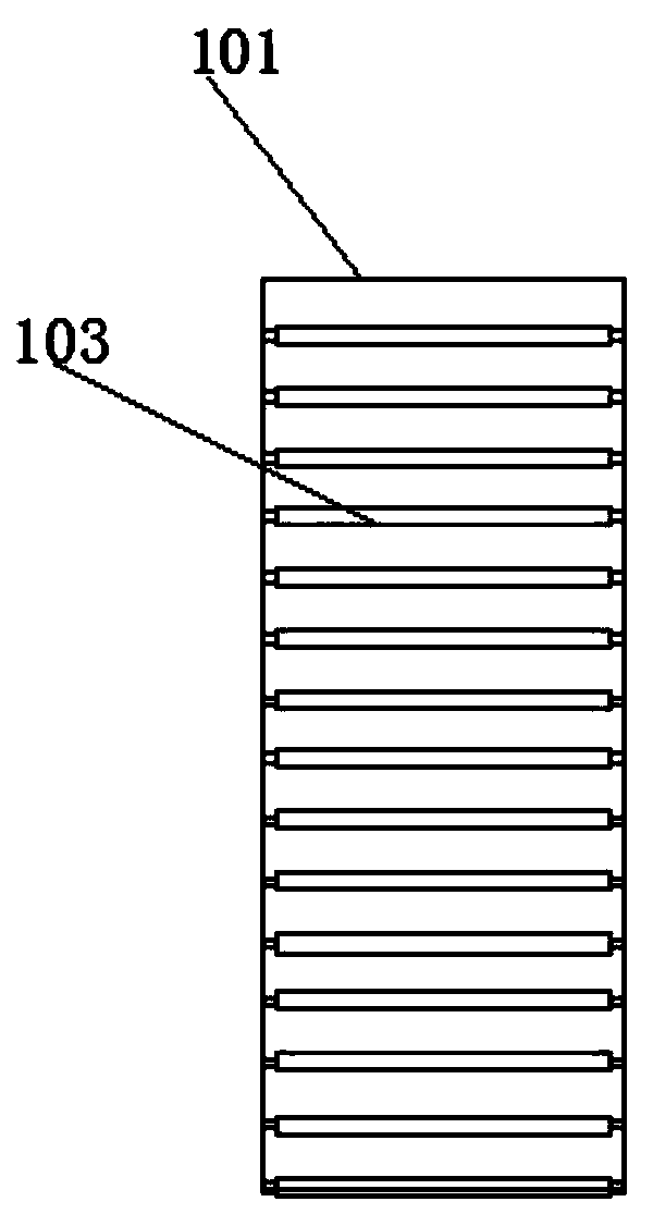
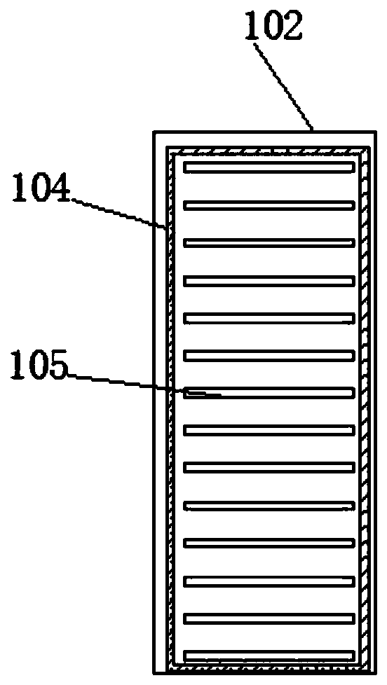
[0029] Such as Figure 1-6 As shown, the present invention provides a technical solution: a brick body angle adjusting device for a fly ash brick conveying device, the brick body angle adjusting device for a fly ash brick conveying device includes a drainage mechanism 1, an adjusting mechanism 2, a fixed Mechanism 3 and driving mechanism 4, both sides of the drainage mechanism 1 are welded with an adjustment mechanism 2, and the adjustment mechanism 2 is provided with two groups, the bottom of one end of the adjustment mechanism 2 is fixedly welded with a fixing mechanism 3, the adjustment mechanism 2. A drive mechanism 4 is fixedly installed on one side, and there are two groups of drive mechanisms 4.

[0030] The drainage mechanism 1 is composed of No. 1 drainage plate 101,...


PUM


Abstract

The invention discloses a brick body angle adjusting device for a fly ash brick conveying device. The brick body angle adjusting device for the fly ash brick conveying device comprises a drainage mechanism, adjusting mechanisms, fixing mechanisms and a driving mechanism, the adjusting mechanisms are welded to the two sides of the drainage mechanism, two sets of adjusting mechanisms are co-arranged, and the fixing mechanisms are fixedly welded at the bottoms of one ends of the adjusting mechanisms. According to the brick body angle adjusting device, angle adjustment is carried out on the fly ash bricks which are placed in groceries, in turn, the fly ash brick is orderly arranged on a conveying belt, and the use is more convenient; the drainage mechanism is simple in structure, good in drainage effect, more convenient to use, and has a buffering effect, and meanwhile, one end of the fly ash brick is dialed through a shifting plate on the surface of a flow guide belt, so that the probability of successful drainage of the fly ash brick can be effectively improved, the clamping frequency of the fly ash brick is reduced, the efficiency of adjusting the angle of the fly ash brick is effectively improved, and the use is more convenient.

Description

technical field [0001] The invention relates to the technical field of fly ash brick conveying equipment, in particular to a brick body angle adjustment device for a fly ash brick conveying device. Background technique [0002] The main raw materials of fly ash bricks are industrial waste solids such as fly ash, lime, gypsum, carbide slag, and carbide mud. It is a solid fly ash brick made of fly ash and lime as the main raw materials, mixed with appropriate amount of gypsum and aggregate, prepared from embryo material, pressed into shape, and cured by high-pressure or normal-pressure steam. Fly ash bricks can be used for walls and foundations of industrial and civil buildings. However, first-class bricks and first-class bricks must be used for foundations or for building parts that are susceptible to freeze-thaw and alternating wet and dry effects. At the same time, fly ash should not be used in parts subject to long-term heating, rapid cooling and rapid heating, and erosi...

Claims


Application Information

Patent Timeline
Patent Type & Authority Applications(China)
IPC IPC(8): B65G47/24
CPCB65G47/24
Inventor 孙伟何建松杨军
Owner 涡阳县晟丰新型建材有限公司
Learn More