
Information transmission method and system and related equipment

A technology for information transmission and control information, applied in wireless communication, electrical components, network planning, etc., can solve the problems of high cost, limited coverage of high-frequency bands, and small coverage radius.

Active Publication Date: 2017-10-24
CHINA MOBILE COMM GRP CO LTD
View PDF4 Cites 0 Cited by
  • Summary
  • Abstract
  • Description
  • Claims
  • Application Information

AI Technical Summary

Problems solved by technology

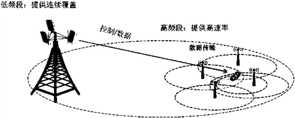
For independent deployment, the disadvantage is that the design of the high-band system is complex, the cost is high, and the coverage of the high-band is limited, which cannot support mobility well
When the user moves, due to the small coverage radius, problems such as frequent switching will occur, which will affect the system performance

Method used


Image

  • Information transmission method and system and related equipment
  • Information transmission method and system and related equipment
  • Information transmission method and system and related equipment

Examples


Embodiment 1

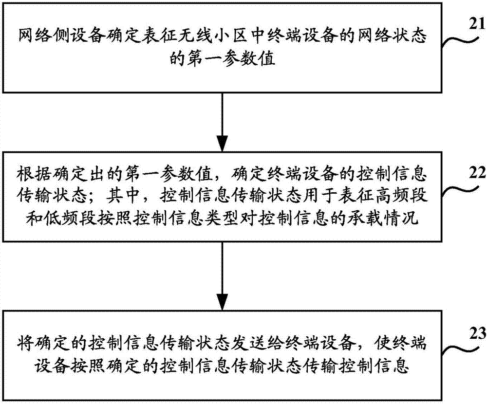
[0124] An embodiment of the present invention provides an information transmission method implemented by a network side device, which is applied to a wireless cell covering both a high frequency band and a low frequency band, such as figure 2 Shown, is the implementation flowchart of this method, specifically comprises the following steps:

[0125] Step 21, the network side device determines a first parameter value representing the network state of the terminal device in the wireless cell.

[0126] In the embodiment of the present invention, the network side equipment may include a macro station BS (low frequency band) and a micro station Pico BS (high frequency band), and the terminal equipment may be referred to as UE (User Equipment) for short.

[0127] Wherein, the first parameter value may at least include one of the following:

[0128] The channel quality, service type and capability level of the terminal equipment.

[0129] Step 22, according to the determined first ...

Embodiment 2

[0158] An embodiment of the present invention provides an information transmission method, which is applied to wireless cells covering both high frequency bands and low frequency bands, such as Figure 5 Shown, is the implementation flowchart of this method, specifically comprises the following steps:

[0159] In step 51, the terminal device acquires a first parameter value representing its own network status.

[0160] Wherein, the first parameter value may at least include one of the following:

[0161] The channel quality, service type and capability level of the terminal equipment.

[0162] Step 52 , according to the determined first parameter value, determine its own control information transmission state; wherein, the control information transmission state is used to represent the carrying condition of the control information by the high frequency band and the low frequency band according to the type of control information.

[0163] For a specific implementation manner ...


PUM


Abstract

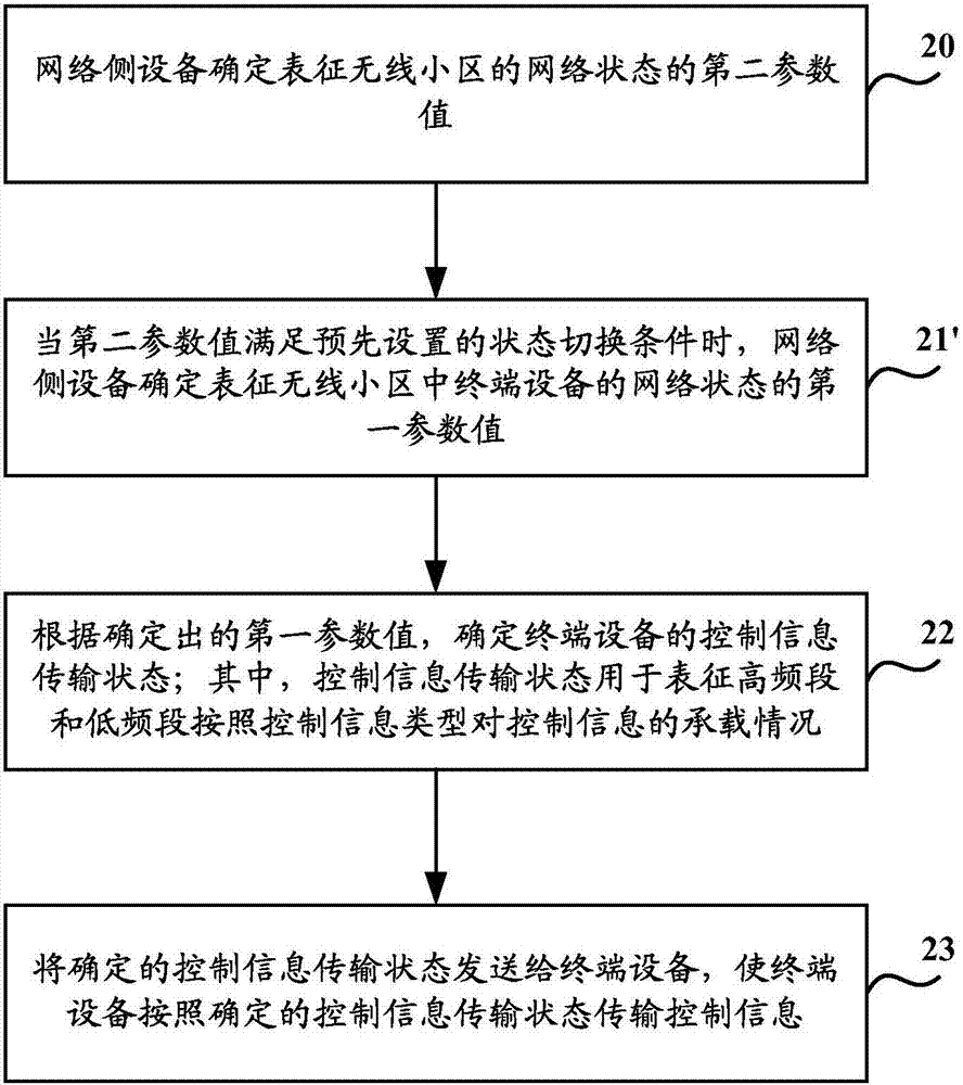
The invention discloses an information transmission method and system and related equipment which realize cooperative transmission between a high frequency band and a low frequency band and improve the system performance. The information transmission method is applied to a wireless cell covering a high frequency band and a low frequency band simultaneously, and comprises the steps that network-side equipment determines a first reference value representing the network state of terminal equipment in the wireless cell; a control information transmission state of the terminal equipment is determined according to the first reference value, wherein the control information transmission state is used for representing bearing conditions of the high frequency band and the low frequency band for control information according to the control information type; and the determined control information transmission state is sent to the terminal equipment.

Description

technical field [0001] The present invention relates to the technical field of wireless communication, in particular to an information transmission method, a related device and a system. Background technique [0002] The 3rd Generation Partnership Project (3rd Generation Partnership Project, 3GPP) Long Term Evolution (LTE) system and its enhanced Long Term Evolution (LTE-Advanced, LTE-A) system are fourth-generation communication systems and standards, and are also The current mainstream standard. In the future, facing the continuous expansion of Internet and Internet of Things business needs, the 5th Generation mobile communication (5G) network has great requirements for delay, coverage, transmission rate, etc., especially for office areas, In dense areas such as stadiums, more frequency bandwidth is required to meet the rate requirements of a large number of users. The existing 4th Generation mobile communication (4G) network (such as LTE or LTE-A) cannot meet the demand...

Claims


Application Information

Patent Timeline
IPC IPC(8): H04W16/04H04W16/14
CPCH04W16/04H04W16/14
Inventor 韩璐胡丽洁
Owner CHINA MOBILE COMM GRP CO LTD
Learn More