Left-right asymmetry type tee pipe internal high pressure forming device

A technology of internal high-pressure forming and tee pipe, which is applied in the field of internal high-pressure forming of pipes, can solve problems such as insufficient feeding, failure of high-pressure expansion type, leakage of high-pressure liquid, etc., and achieve the effect of avoiding insufficient feeding and preventing shock cracks

Inactive Publication Date: 2017-11-03
柳州科瑞科技有限公司 +1
View PDF7 Cites 1 Cited by
  • Summary
  • Abstract
  • Description
  • Claims
  • Application Information

AI Technical Summary

Problems solved by technology

[0004] 1. Existing internal high pressure forming equipment for pipes is used to control the forced displacement of the left and right thrust cylinders to carry out axial feeding when making parts. This active and compulsory mechanical feeding method is difficult to match the deformation of the blank. In the process of mold forming, it is easy to cause insufficient or excessive feeding, and it is difficult to reasonably control the amount of feeding, and it is difficult to control;
[0005] 2. By artificially setting the feed amount, that is, controlling the displacement of the left and right thrust cylinders to feed the feed, it is easy to cause insufficient feed amount, which leads to the phenomenon of cracking due to insufficient feed and untimely filling during the expansion process, resulting in high pressure expansion. type failure;
[0006] 3. The sensitivity of feeding control is not high, and it is also easy to cause the rapid deformation of the tube blank due to the internal pressure of the tube blank reaching the material yield point during the forming process, causing the material at the two ends of the tube to quickly flow into the mold cavity, which is easy to produce tube The two ends of the mouth are separated from the left and right push heads, resulting in the leakage of the high-pressure liquid that has been established inside the tube blank, and the most fundamental internal high-pressure forming conditions cannot be guaranteed;
[0007] 4. Excessive feeding will easily lead to forming defects such as wrinkling, wrinkles, and thickening of the parts in the forming area, resulting in the failure of the parts to bulge

Method used


Image

  • Left-right asymmetry type tee pipe internal high pressure forming device
  • Left-right asymmetry type tee pipe internal high pressure forming device

Examples


Embodiment 1

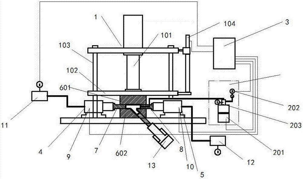
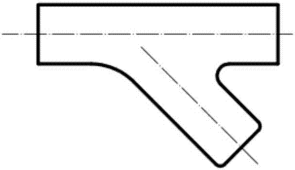
[0026] A left and right asymmetric tee pipe internal high pressure forming equipment, such as Figure 1-2 As shown, the internal high pressure forming equipment includes a clamping press (1), a booster system (2), an electrical control system (3), an upper mold (601), a lower mold (602), a left oil pump (11), Right oil pump (12), left push head (7), right push head (8) installed on the workbench, left thrust cylinder (4), right thrust cylinder (5), material support cylinder (13); wherein, the upper The mold (601) is installed on the movable beam (102) of the clamping press and is connected with the main cylinder (101) of the press through the movable beam (102) and the guide column (103). The cylinders are connected, the guide column (103) is connected with the beam displacement transmission (104), the left and right thrust cylinders are respectively connected with the left cylinder hydraulic pressure sensor (9), the right cylinder hydraulic pressure sensor (10), the booster s...


PUM


Abstract

The invention discloses a left-right asymmetric three-way pipe internal high-pressure forming equipment. The internal high-pressure forming equipment comprises a clamping press, a booster system, an electrical control system, an upper die, a lower die, a left oil pump, a right oil pump, The left push head, right push head, left push cylinder, right push cylinder and material support cylinder installed on the worktable; this equipment ensures that the high pressure inside the pipe will not fail during the forming process, and avoids the pipe forming during the forming process. At the same time, it also avoids the phenomenon that the pipe material is not replenished in time and bursts when the rapid deformation occurs, and finally ensures the stable realization of the gradual forming and shaping of the pipe parts.

Description

technical field [0001] The invention belongs to the technical field of internal high-pressure forming of pipes, in particular to a left-right asymmetric three-way internal high-pressure forming equipment for pipes. Background technique [0002] The principle of internal high-pressure forming of pipes is: after the upper and lower molds are closed, the pipe is sealed by the left and right push heads and the pressure forming medium is injected into the pipe, and the internal pressure of the pipe is realized under the joint action of the left and right push heads and the internal pressure. take shape. Compared with the traditional processing technology, the parts obtained by this forming method have a series of advantages such as low cost, light weight, material saving, less processing steps, high forming quality, good mechanical properties, and high rigidity and strength. [0003] The problems existing in the existing pipe internal high pressure forming equipment are: [000...

Claims


Application Information

Patent Timeline
Patent Type & Authority Applications(China)
IPC IPC(8): B21D26/037B21D26/039B21D26/045
CPCB21D26/037B21D26/039B21D26/045
Inventor 刘泽彬李健梁雷宋豪梁宁龙怡璇朱洁
Owner 柳州科瑞科技有限公司
Why Eureka
Try Eureka