Suction pressure type hydropower station

A technology for hydropower stations and water suction pipes, which is applied in the directions of hydropower generation, engine components, machines/engines, etc., to achieve the effect of large power generation and low construction cost

Pending Publication Date: 2017-11-03
解秀忠
View PDF5 Cites 6 Cited by
  • Summary
  • Abstract
  • Description
  • Claims
  • Application Information

AI Technical Summary

Problems solved by technology

[0002] Existing hydroelectric power stations, the hydroelectric generating units located in the dam body, only utilize the water delivery channel and the pressure of the water surface drop in the dam to act on the water turbine driving the generator in the water delivery channel to generate electricity. For the water turbine outlet The subsequent water flow has not been utilized, and there is no suction hydraulic system that can not only use the water pressure formed from the water delivery channel to the water surface of the dam, but also use the water flow outside the water outlet of the turbine to create a drop and act on the generator set to drive the generator set to generate more electric energy. power station

Method used


Image

  • Suction pressure type hydropower station
  • Suction pressure type hydropower station
  • Suction pressure type hydropower station

Examples


Embodiment

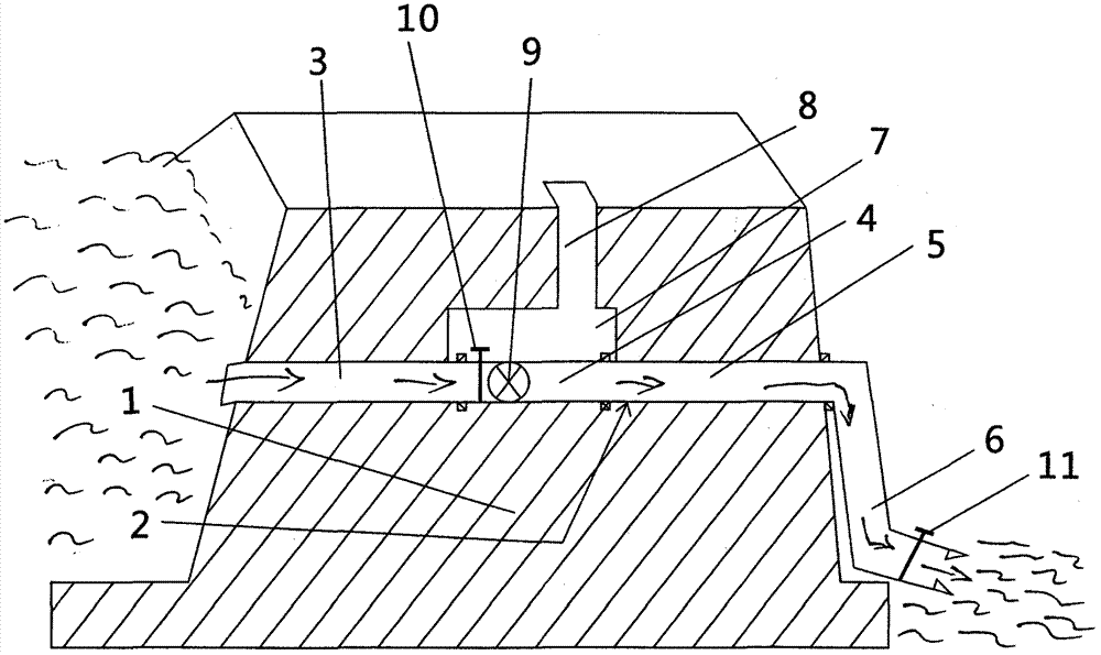
[0063] Example: Suction-pressure type external downstream pipeline hydropower station

[0064] Such as figure 1 : Pressure-suction type external down-pipeline hydropower station, the structure is a concrete structure dam body (1), the dam body (1) is provided with water delivery channels (2) through both sides of the dam body, and the water delivery channels (2) are divided into water in turn Section (3), installed section (4), outlet section (5) and external downstream outlet section (6) are provided with valves (11) at the outlets, and installed section (4) in the water delivery channel (2) in the dam body (1) ) Is provided with a machine room (7) and a machine room passage (8), and the installation section (4) is provided with a valve (10) and a turbine of the generator set (9).


PUM


Abstract

The invention discloses a suction pressure type hydropower station and relates to the field of hydroelectric generation. A dam is built to increase the water level in the dam to impact a generator set arranged in a water conveying channel in the dam through fall head water flow, a downward pipeline and an extending pipeline of the water conveying channel are arranged to remove air in the pipeline, suction pressure produced through increasing of the water surface fall head of the water outlets of the downward pipeline and the extending pipeline acts on the generator set in the water conveying pipeline, the number of generator sets adapting to the water conveying pipeline can be increased according to the practical fall head, namely water flow force, and electric capacity can also be increased. The suction pressure type hydropower station has the advantages that building is easy, the cost is low, and hydropower stations in appropriate areas can be used for power generation and water conveying.

Description

Technical field [0001] The present invention relates to the field of hydroelectric power stations, in particular to hydroelectric power stations that can increase the water level drop. Background technique [0002] The existing hydroelectric power station, the hydroelectric generator set in the dam body, only uses the water delivery channel and the water surface pressure in the dam to act on the water flow in the water channel to drive the generator to generate electricity. For the water outlet of the water turbine The subsequent water flow has not been used, and there is no suction pressure hydraulic power that can not only use the water pressure formed by the water conveyance channel to the water surface of the dam, but also use the water flow outside the water turbine outlet to create a drop. The resultant force acts on the turbine to drive the generator set to generate more electricity. Power station. Summary of the invention [0003] The purpose of the present invention is t...

Claims


Application Information

Patent Timeline
Patent Type & Authority Applications(China)
IPC IPC(8): F03B13/08
CPCF03B13/086Y02E10/20
Inventor 解秀忠
Owner 解秀忠
Why Eureka
Try Eureka