Vacuum anti-blocking urinal

An anti-clogging and urinal technology, applied in buildings, water supply devices, urinals, etc., can solve the problem of incompatibility between drainage speed and anti-clogging, and achieve the effects of preventing urine splashing, good anti-clogging, and good filtering effect

Inactive Publication Date: 2019-07-09
孟祥娣
View PDF6 Cites 2 Cited by
  • Summary
  • Abstract
  • Description
  • Claims
  • Application Information

AI Technical Summary

Problems solved by technology

[0003] The technical problem to be solved by the present invention is to provide a vacuum anti-clogging urinal, which solves the problem that the drainage speed and anti-clogging of urinals in the existing market cannot be balanced. specialty

Method used


Image

  • Vacuum anti-blocking urinal
  • Vacuum anti-blocking urinal
  • Vacuum anti-blocking urinal

Examples


Embodiment Construction

[0028] The principles and features of the present invention are described below in conjunction with the accompanying drawings, and the examples given are only used to explain the present invention, and are not intended to limit the scope of the present invention.

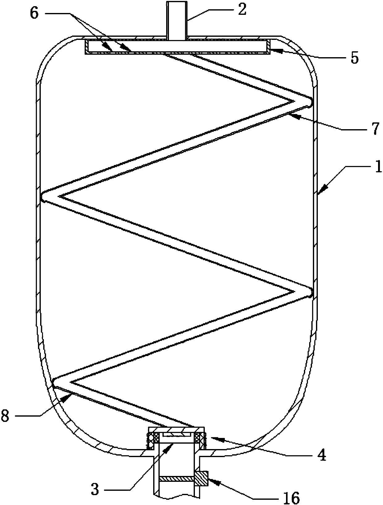
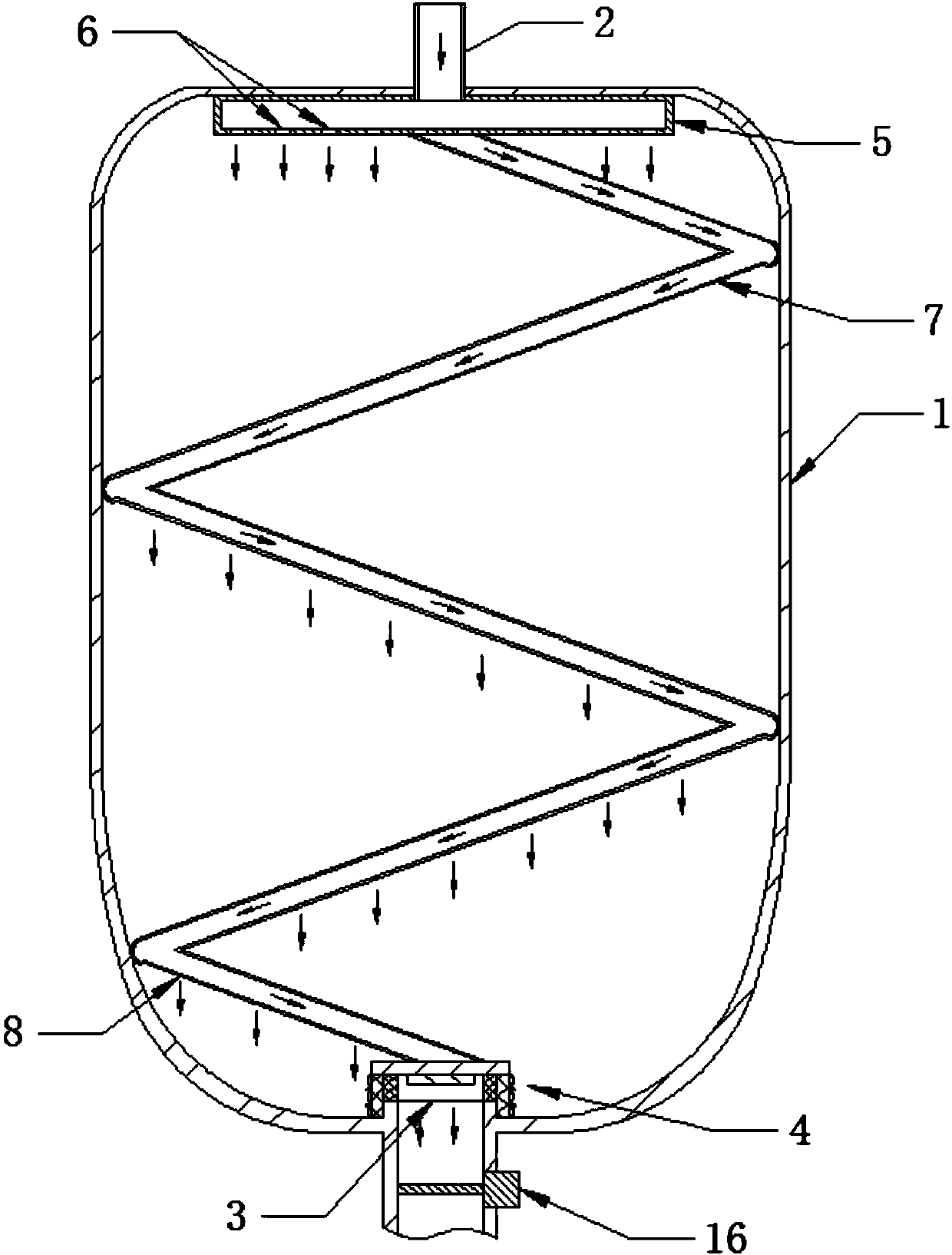
[0029] Such as Figure 1~6 The vacuum anti-clogging urinal shown includes a pool body 1, a water inlet 2 located at the upper end of the pool body 1, a water outlet 3 located at the lower end of the pool body 1, and an anti-blocking cover 4 located at the water outlet 3, the pool body The upper end of 1 is close to the water inlet 2. There is a diversion chamber 5; A wave-shaped buffer tube 7 vertically running is provided; the inlet end of the buffer tube 7 communicates with the flow distribution chamber 5 through the straight hole 6, and the lower wall of the buffer tube 7 is provided with a plurality of buffer holes 8;

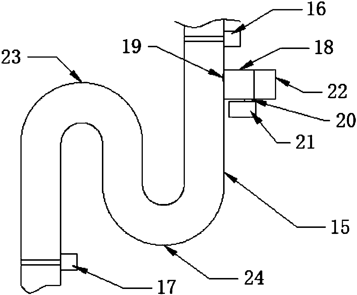
[0030] The anti-blocking cover 4 includes a cover body 9, a fine filter ring 10 disposed at ...


PUM


Abstract

The invention relates to a vacuum anti-blocking urinal. The vacuum anti-blocking urinal comprises a urinal body, a water inlet formed in the upper end of the urinal body, a water outlet formed in thelower end of the urinal body, and an anti-blocking cover arranged on the water outlet. A shunting chamber is arranged at the position, close to the water inlet, of the upper end of the urinal body. The upper end of the shunting chamber is communicated with the water inlet, and multiple direct drain holes are formed in the lower end of the shunting chamber. A vertical wavy buffer pipe is further arranged between the water inlet and the water outlet of the urinal body. The inlet end of the buffer pipe is communicated with the shunting chamber through the direct drain holes, and multiple buffer holes are formed in the lower wall of the buffer pipe. Under the effect of the vertical wavy buffer pipe, as the buffer holes are formed in the lower wall of the buffer pipe, during flushing, currentsflow down from the buffer holes in a classified and layered mode, the fall of the currents is reduced, and splashing caused by the high fall is avoided.

Description

technical field [0001] The invention relates to a urinal, in particular to a vacuum anti-clogging urinal. Background technique [0002] Existing urinals usually adopt a simple flushing structure and are equipped with an anti-blocking cover with simple structure and function. However, the existing urinal flushing method is not only not clean, but also the water is slow. After flushing, the mixed liquid of urine and water will accumulate at the bottom of the urinal, and it will be discharged slowly, which will affect the senses and cause the odor to spread. In the air, it brings discomfort to people. The existing urinal structure leads to the sacrifice of its anti-clogging effect if the drainage speed needs to be accelerated, causing foreign objects such as cigarette butts and hair to enter the drain and cause blockage; if the anti-clogging effect needs to be strengthened, the drainage speed will be lower; In addition, the common flushing method of the existing urinals easil...

Claims


Application Information

Patent Timeline
Patent Type & Authority Applications(China)
IPC IPC(8): E03D13/00
CPCE03D13/00E03D13/005
Inventor 不公告发明人
Owner 孟祥娣
Why Eureka
Try Eureka