Valve body with filtering function

A valve body and function technology, applied in the field of valve body with filtering function, can solve the problems of poor sealing of valve body joints, lower pressure on the water outlet side of the valve body, and increased maintenance and repair costs, so as to improve normal use, Prevent tube explosion and reduce maintenance and repair costs

Active Publication Date: 2019-08-13
浙江鑫泰阀门科技有限公司
View PDF7 Cites 8 Cited by
  • Summary
  • Abstract
  • Description
  • Claims
  • Application Information

AI Technical Summary

Problems solved by technology

[0002] Usually, when watering farmland crops, it is necessary to use water pipelines to transport long-distance water sources to the fields that need to be irrigated. Due to the limited length of water pipelines, valve bodies that play a role in connection are usually used at the connections The ends of the two water delivery pipelines are connected and communicated with each other. When the water source passes through the pipeline, the water quality contains impurities, such as mud, floating objects, etc., which can easily block the valve body, resulting in a decrease in the pressure on the outlet side of the valve body. The water output is reduced, thereby reducing the irrigation efficiency, and the flow rate of the water inlet side of the valve body becomes smaller due to blockage, so the pressure gradually increases. On the one hand, the sealing of the valve body connection will become poor, damaged, and even burst. It will lead to an increase in maintenance and repair costs and aggravate the reduction in efficiency. In view of this, we propose a valve body with filtering function

Method used


Image

  • Valve body with filtering function
  • Valve body with filtering function
  • Valve body with filtering function

Examples


Embodiment Construction

[0025] The following will clearly and completely describe the technical solutions in the embodiments of the present invention with reference to the accompanying drawings in the embodiments of the present invention. Obviously, the described embodiments are only some, not all, embodiments of the present invention. Based on the embodiments of the present invention, all other embodiments obtained by persons of ordinary skill in the art without creative efforts fall within the protection scope of the present invention.

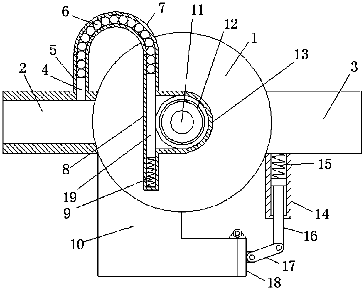
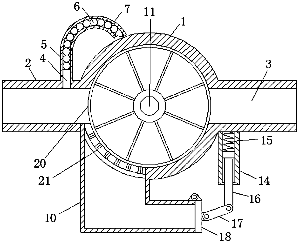
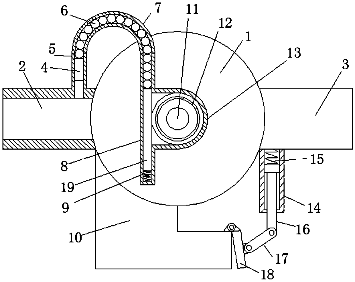
[0026] see Figure 1-4 , the present invention provides a technical solution: a valve body with filtering function, including a valve housing 1, the left and right sides of the valve housing 1 are respectively fixed with a water inlet connecting pipe 2 and an outlet water connecting pipe 3, and the water inlet connecting pipe 2 and the water outlet connecting pipe 3 are connected with the valve casing 1, the inner center of the valve casing 1 is fixedly rotated and...


PUM


Abstract

The invention relates to the field of water control valves, in particular to a valve body with a filtering function. The valve body comprises a valve shell, wherein the left and right sides of the valve shell are fixedly provided with a water inlet connecting pipe and a water outlet connecting pipe respectively, the center of the inner portion of the valve shell is rotatably in fixed-axis connection with a rotating shaft, the rotating shaft is fixedly provided with a filter net, the water inlet connecting pipe is connected with an intermittent reciprocating mechanism and is connected with therotating shaft through the intermittent reciprocating mechanism, the lower side of the valve shell is fixedly provided with a discharge pipe, the joint of the discharge pipe and the valve shell is fixedly provided with a brush frame cleaning the filter net, and an outlet end of the discharge pipe is provided with an automatic discharge mechanism. The valve body with the filtering function can automatically perform cleaning, keep the stable discharge value of the filter net and improve the water delivery efficiency so that the water pressure in the valve body can be kept stable in time, therefore, structural parts in the valve body are not damaged by the excessive water pressure, the pipe is also prevented from being broken, automatic discharge can also be achieved, and the time and labor are saved.

Description

technical field [0001] The invention relates to the field of water control valves, in particular to a valve body with a filtering function. Background technique [0002] Usually, when watering farmland crops, it is necessary to use water pipelines to transport long-distance water sources to the fields that need to be irrigated. Due to the limited length of water pipelines, valve bodies that play a role in connection are usually used at the connections The ends of the two water delivery pipelines are connected and communicated with each other. When the water source passes through the pipeline, the water quality contains impurities, such as mud, floating objects, etc., which can easily block the valve body, resulting in a decrease in the pressure on the outlet side of the valve body. The water output is reduced, thereby reducing the irrigation efficiency, and the flow rate of the water inlet side of the valve body becomes smaller due to blockage, so the pressure gradually incr...

Claims


Application Information

Patent Timeline
Patent Type & Authority Applications(China)
IPC IPC(8): B01D35/02B01D35/16F16K51/00
CPCB01D35/02B01D35/16F16K51/00
Inventor 王拓
Owner 浙江鑫泰阀门科技有限公司
Why Eureka
Try Eureka