A wire saw injection molding machine

A technology of injection molding machine and wire saw, applied in the direction of coating, etc., can solve the problems that the injection position deviates from the correct position, affects the injection quality, and it is difficult to ensure the tension of the steel wire rope, etc., and achieves the effect of improving the injection quality

Active Publication Date: 2019-01-22
东莞市今通塑胶机械有限公司
View PDF3 Cites 0 Cited by
  • Summary
  • Abstract
  • Description
  • Claims
  • Application Information

AI Technical Summary

Problems solved by technology

[0004] However, for the existing injection molding machines, the steel wire rope is often conveyed in a straight line during the beading injection molding process of the wire saw, but it is difficult to ensure the tension of the steel wire rope during the transmission process, and it is easy to cause the actual injection position to deviate from the correct position. , affect the injection molding effect
In addition, there is not enough space for cooling after injection molding, which easily affects the quality of injection molding

Method used


Image

  • A wire saw injection molding machine
  • A wire saw injection molding machine
  • A wire saw injection molding machine

Examples


Embodiment Construction

[0018] The present invention will be further elaborated below in conjunction with accompanying drawing:

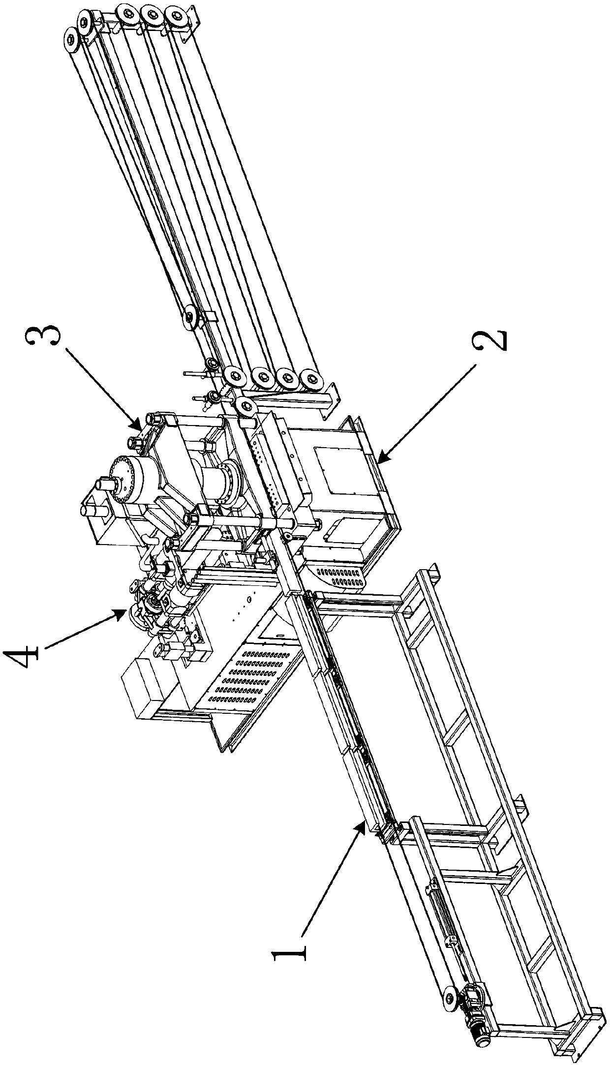
[0019] Such as figure 1 As shown, the wire saw injection molding machine includes: a transmission mechanism 1 , a workbench 2 , a positioning mechanism 3 and an injection molding mechanism 4 . The conveying mechanism 1 is used for conveying the wire saw, the positioning mechanism 3 is used for fixing the mould, and the injection molding mechanism 4 is used for injection molding the wire rope and the beads, wherein the positioning mechanism 3 and the injection molding mechanism 4 are located on the workbench 2 . The conveying mechanism 1 includes a mould, the injection molding mechanism 4 has an injection port for injection molding material, the mold is fixed between the positioning mechanism 3 and the worktable 2, and the injection port of the injection molding mechanism 4 is aligned with the mould.

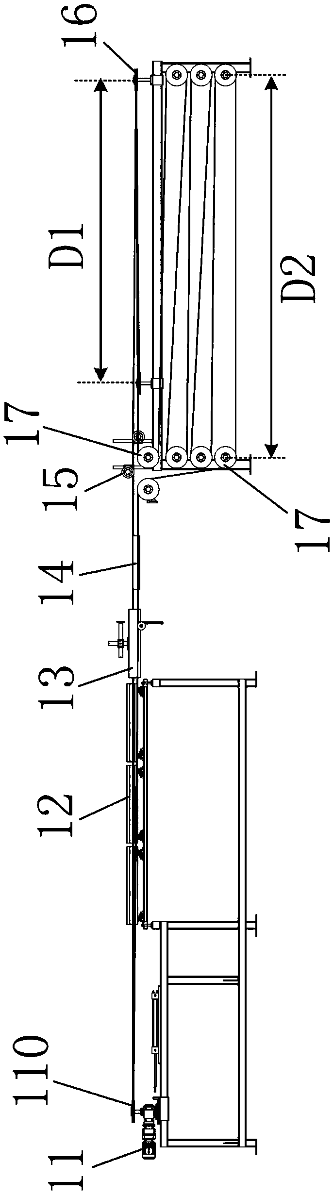
[0020] Such as figure 2 As shown, the transmission mechanism 1 includ...


PUM


Abstract

The invention relates to a rope saw injection molding machine which comprises a transmission mechanism, a work table, a positioning mechanism and an injection molding mechanism. The positioning mechanism and the injection molding mechanism are located on the work table. The injection molding mechanism is provided with an ejection port. The transmission mechanism comprises a transmission motor, a mold, a tensioning wheel, a plurality of transverse transmission wheels and a plurality of longitudinal transmission wheels. The transmission motor is provided with a power wheel, and a closed loop is formed in the mode that a rope saw sequentially passes through the power wheel, the mold and the tensioning wheel and surrounds the transverse transmission wheels and the longitudinal transmission wheels. The mold is fixed between the positioning mechanism and the work table. The ejection port of the injection molding mechanism is aligned at the mold. According to the rope saw injection molding machine, steel wire rope tensioning can be ensured in the rope saw transmission process, the situation that the sufficient cooling time for the rope saw is ensured after injection molding is completed, and the injection molding quality of the rope saw is greatly improved.

Description

technical field [0001] The invention relates to a wire saw injection molding machine. Background technique [0002] Wire saw is a cutting demolition equipment for thick concrete and irregular concrete. For example: for the cutting of concrete structures such as girders, supports, and high-speed rail piers, the use of wire saws is flexible, and both horizontal and vertical cutting are acceptable. [0003] Some current wire saws carry out injection molding of steel wire rope and beads by injection molding machine. For example, Chinese patent CN101011853 discloses a diamond wire saw injection molding device. Optimum temperature for easy handling. [0004] However, for the existing injection molding machines, the steel wire rope is often conveyed in a straight line during the beading injection molding process of the wire saw, but it is difficult to ensure the tension of the steel wire rope during the transmission process, and it is easy to cause the actual injection position t...

Claims


Application Information

Patent Timeline
Patent Type & Authority Patents(China)
IPC IPC(8): B29C45/14B29C45/17B29C33/12B29C33/30B29C45/26
CPCB29C45/14016B29C45/14065B29C45/2606
Inventor 何昌诚
Owner 东莞市今通塑胶机械有限公司
Why Eureka
Try Eureka