

Fast joint-cutting apparatus for traffic road pavement
A road pavement, fast technology, applied in the direction of road, road, road repair, etc., can solve the problems such as dust is not easy to fly, cutting speed is slow, dust is easy to fly, etc.
- Summary
- Abstract
- Description
- Claims
- Application Information
AI Technical Summary
Problems solved by technology
Method used
Image

Examples
Embodiment 1
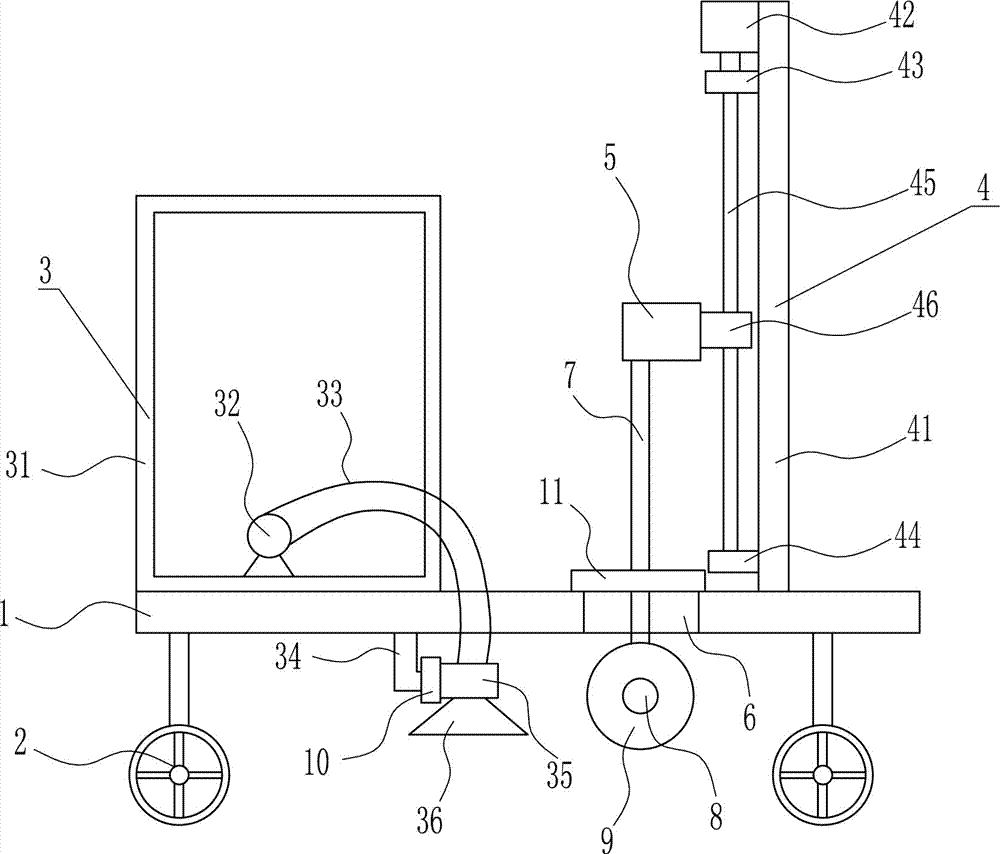
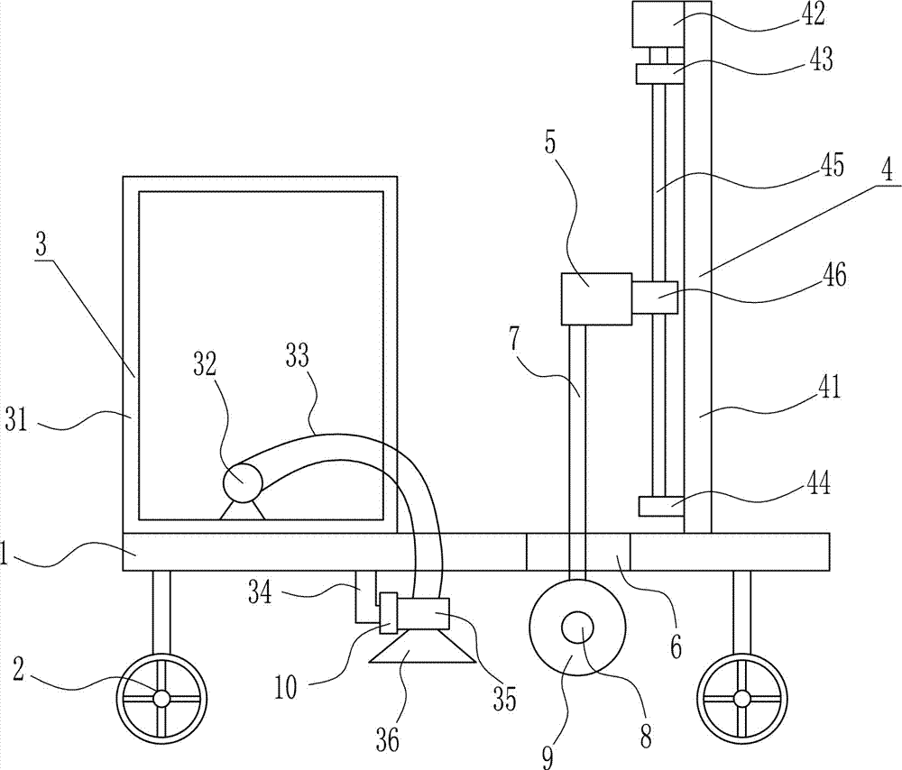
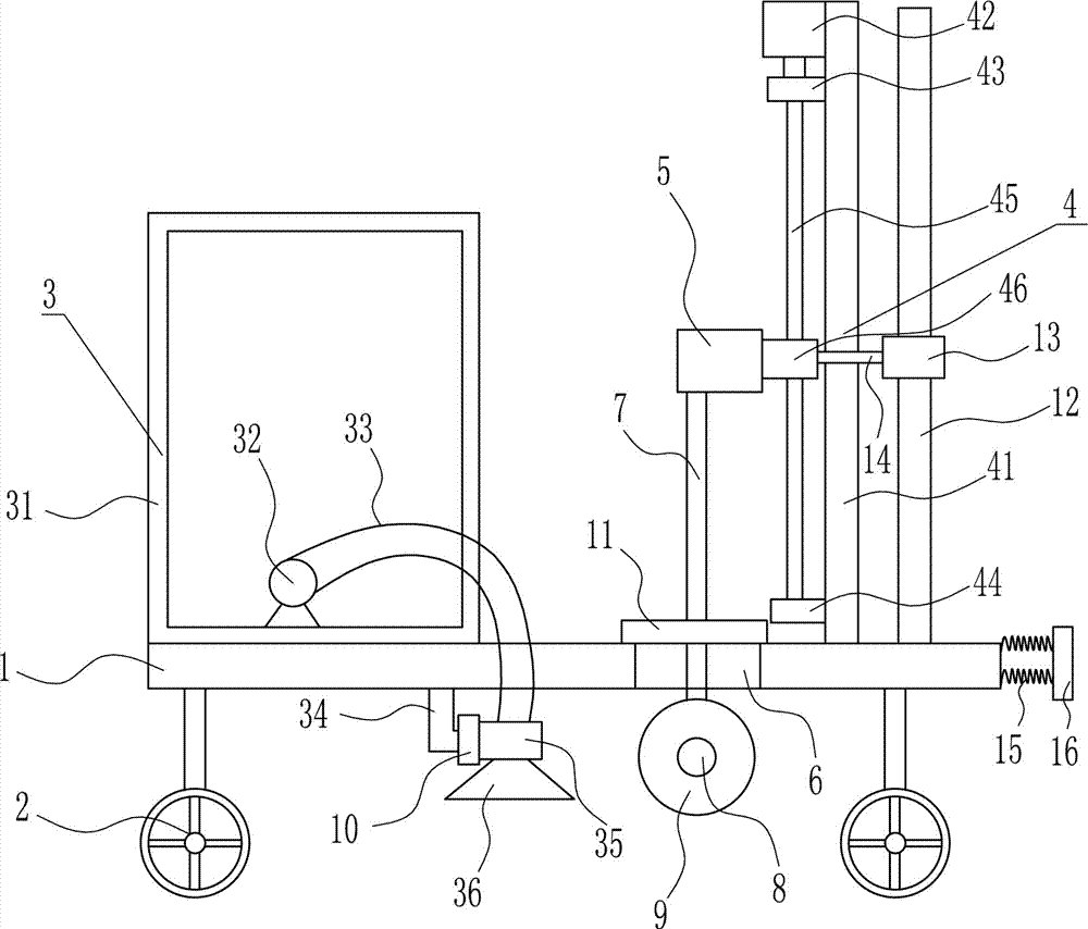
[0036] A kind of road pavement fast cutting and seaming device for traffic, such as Figure 1-7 As shown, it includes a plate, a wheel 2, a water spray device 3, an adjustment device 4, a connecting block 5, a lifting rod 7, a second motor 8 and a cutting blade 9, the bottom of the base plate 1 is provided with the wheel 2, and the left side of the top of the base plate 1 is provided with There is a water spray device 3, an adjustment device 4 is provided on the top right side of the bottom plate 1, a connecting block 5 is provided on the left side of the adjustment device 4, a lifting rod 7 is provided at the bottom of the connecting block 5, a through hole 6 is opened in the middle of the bottom plate 1, and a lifting rod 7 Through the through hole 6 , a second motor 8 is mounted on the bottom of the lifting rod 7 , and a cutting blade 9 is connected to the output shaft of the second motor 8 .
Embodiment 2
[0038] A kind of road pavement fast cutting and seaming device for traffic, such as Figure 1-7As shown, it includes a plate, a wheel 2, a water spray device 3, an adjustment device 4, a connecting block 5, a lifting rod 7, a second motor 8 and a cutting blade 9, the bottom of the base plate 1 is provided with the wheel 2, and the left side of the top of the base plate 1 is provided with There is a water spray device 3, an adjustment device 4 is provided on the top right side of the bottom plate 1, a connecting block 5 is provided on the left side of the adjustment device 4, a lifting rod 7 is provided at the bottom of the connecting block 5, a through hole 6 is opened in the middle of the bottom plate 1, and a lifting rod 7 Through the through hole 6 , a second motor 8 is mounted on the bottom of the lifting rod 7 , and a cutting blade 9 is connected to the output shaft of the second motor 8 .
[0039] Sprinkler 3 includes water tank 31, water pump 32, flexible pipe 33, L-sha...
Embodiment 3
[0041] A kind of road pavement fast cutting and seaming device for traffic, such as Figure 1-7 As shown, it includes a plate, a wheel 2, a water spray device 3, an adjustment device 4, a connecting block 5, a lifting rod 7, a second motor 8 and a cutting blade 9, the bottom of the base plate 1 is provided with the wheel 2, and the left side of the top of the base plate 1 is provided with There is a water spray device 3, an adjustment device 4 is provided on the top right side of the bottom plate 1, a connecting block 5 is provided on the left side of the adjustment device 4, a lifting rod 7 is provided at the bottom of the connecting block 5, a through hole 6 is opened in the middle of the bottom plate 1, and a lifting rod 7 Through the through hole 6 , a second motor 8 is mounted on the bottom of the lifting rod 7 , and a cutting blade 9 is connected to the output shaft of the second motor 8 .
[0042] Sprinkler 3 includes water tank 31, water pump 32, flexible pipe 33, L-sh...
PUM
 Abstract
Description
Claims
Application Information