A humidity control method and device
A humidity control and unit control technology, which is applied to control input related to air characteristics, space heating and ventilation control input, heating mode, etc., can solve problems such as low reliability and accuracy, waste of electricity, water and other resources
- Summary
- Abstract
- Description
- Claims
- Application Information
AI Technical Summary
Problems solved by technology
Method used
Image
Examples
Embodiment 1
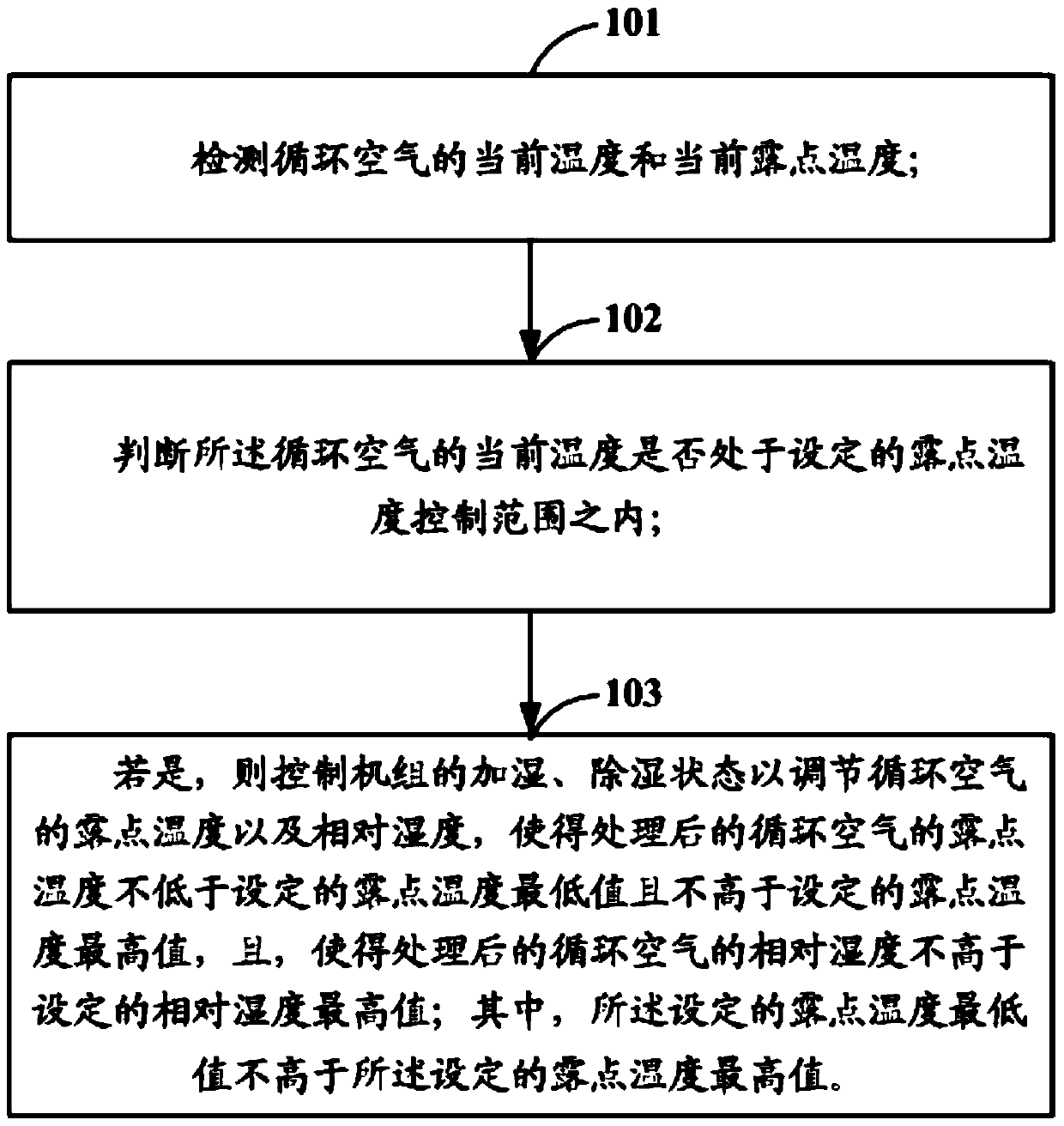
[0088] Embodiment 1 of the present invention provides a humidity control method, specifically, as figure 1 As shown, it is a schematic flow chart of the humidity control method described in Embodiment 1 of the present invention, and the method includes:
[0089] Step 101: Detect the current temperature and the current dew point temperature of the circulating air.
[0090] Optionally, a temperature sensor or a temperature and humidity sensor may be used to detect the current temperature of the circulating air.
[0091] In addition, it should be noted that since the current dew point temperature of the circulating air cannot be directly detected by the sensor, and its value is related to the temperature and relative humidity of the circulating air, the temperature sensor or the temperature and humidity sensor can detect the temperature of the circulating air. The current temperature and the current relative humidity of the circulating air detected by the humidity sensor or the ...
example 1
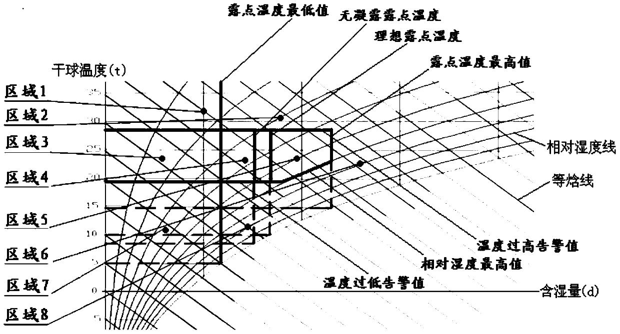
[0143] Suppose, before controlling the temperature and humidity in the computer room, set the minimum dew point temperature, the maximum dew point temperature, the maximum relative humidity, the ideal dew point temperature, the relative humidity target value, the low temperature alarm value, and the high temperature alarm value ;Among them, the lowest value of dew point temperature<ideal dew point temperature<the highest value of dew point temperature, the target value of relative humidity<the highest value of relative humidity, the alarm value of low temperature<the alarm value of high temperature; and set the first boundary of the control range of dew point temperature Infinitely lower than the low temperature alarm value, and the second boundary is infinitely higher than the high temperature alarm value; and when setting the temperature and humidity control, it is necessary to refer to the ideal dew point temperature, the control process is as follows:
[0144] Step 1: Detec...
example 2
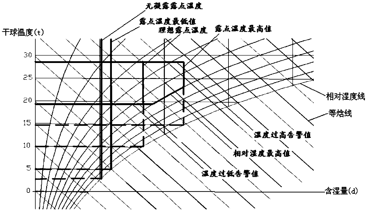
[0176] Assume, before controlling the temperature and humidity in the computer room, set the minimum value of dew point temperature, the maximum value of dew point temperature, the maximum value of relative humidity, the target value of relative humidity, the alarm value of too low temperature, and the alarm value of too high temperature; among them, dew point The lowest temperature value<the highest dew point temperature value, the relative humidity target value<the highest relative humidity value, the low temperature alarm value<the high temperature alarm value; and the first boundary of the dew point temperature control range is set to be equal to the low temperature alarm value , and the second boundary is equal to the high temperature alarm value; and when the temperature and humidity control is set, without reference to the ideal dew point temperature, the control process is as follows:
[0177] Step 1: Detect the current temperature and current dew point temperature of t...
PUM
 Abstract
Description
Claims
Application Information
 - R&D
- Intellectual Property
- Life Sciences
- Materials
- Tech Scout
- Unparalleled Data Quality
- Higher Quality Content
- 60% Fewer Hallucinations
Browse by: Latest US Patents, China's latest patents, Technical Efficacy Thesaurus, Application Domain, Technology Topic, Popular Technical Reports.
© 2025 PatSnap. All rights reserved.Legal|Privacy policy|Modern Slavery Act Transparency Statement|Sitemap|About US| Contact US: help@patsnap.com


