A time-delayed dead-end shotgun and shotgun

A technology without dead ends and shotguns, applied in the directions of warheads, ammunition, weapon accessories, etc., can solve the problem of inability to strike at medium and long-range targets, and achieve the effect of improving safety and avoiding potential safety hazards.

Active Publication Date: 2019-03-19
来安县永阳知识产权运营有限公司
View PDF5 Cites 0 Cited by
  • Summary
  • Abstract
  • Description
  • Claims
  • Application Information

AI Technical Summary

Problems solved by technology

[0005] Therefore, the technical problem to be solved by the present invention is to overcome the technical defect that the shotgun in the prior art cannot strike medium and long-range targets

Method used


Image

  • A time-delayed dead-end shotgun and shotgun
  • A time-delayed dead-end shotgun and shotgun
  • A time-delayed dead-end shotgun and shotgun

Examples


Embodiment 1

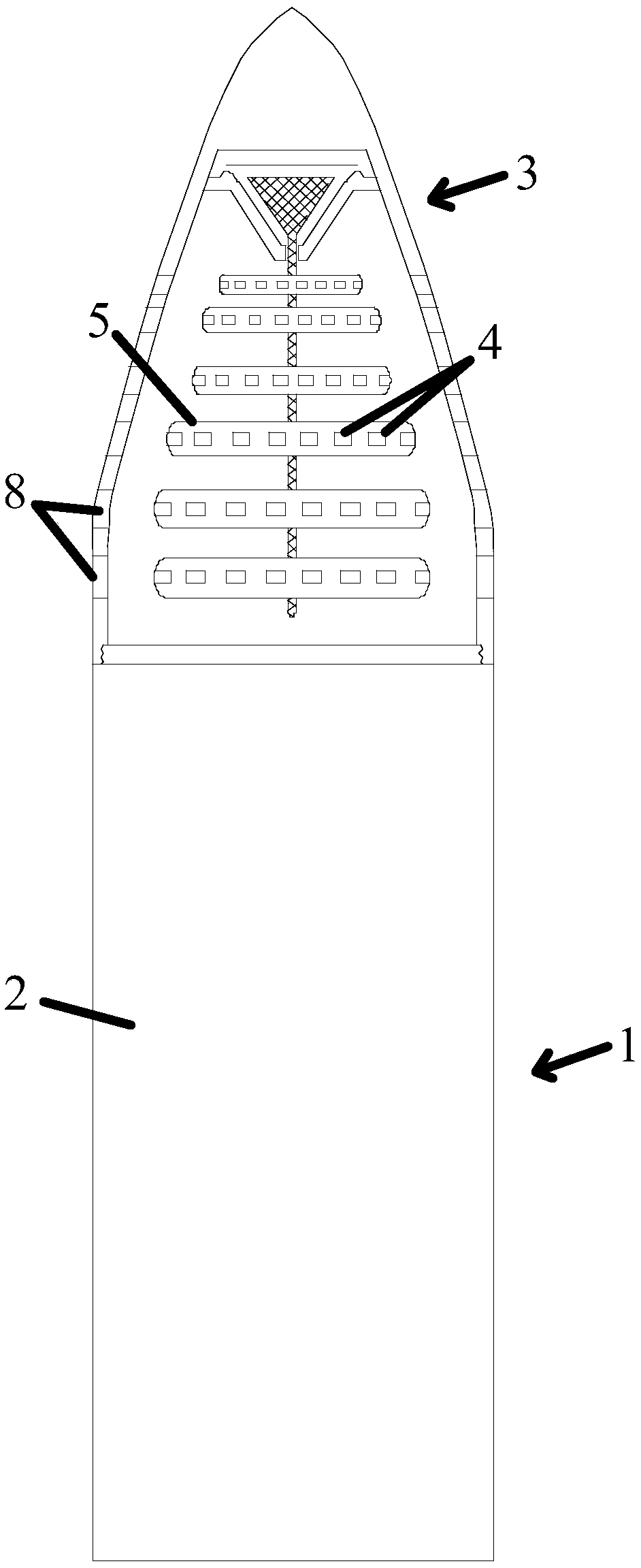
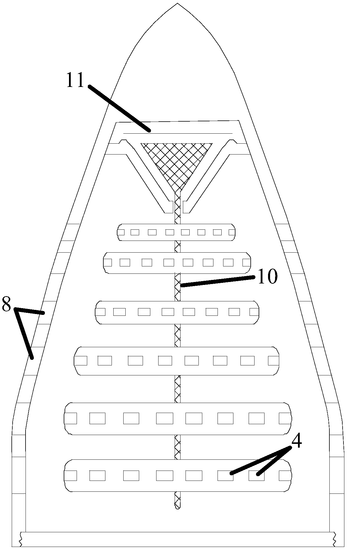
[0037] Such as figure 1 and figure 2 Delayed detonation no-dead shotguns shown, including:

[0038] The shotgun body 1 is provided with a primary motive medium 2 in the cavity of the shotgun body 1;

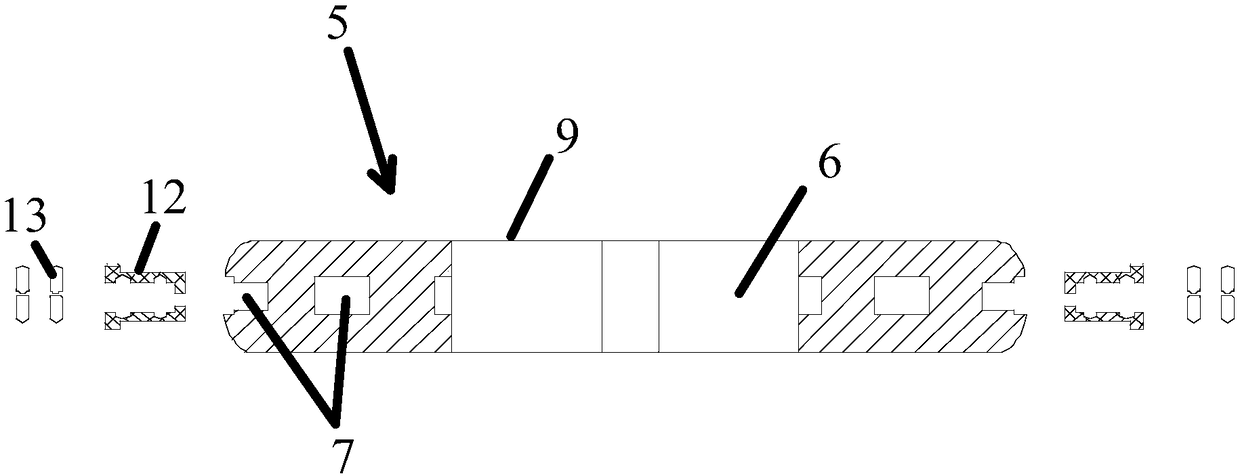
[0039] The shotgun 3 is arranged on the front end of the shotgun body 1. At least one body chamber 5 containing several bullets 4 is arranged in the inner cavity of the shotgun 3. The body chamber 5 is provided with a secondary power for exciting the bullets 4. medium 6 and an excitation structure for receiving excitation control instructions to excite the secondary motive medium 6;

[0040] The casing of the projectile chamber 5 is provided with a number of first firing holes 7 for guiding the firing direction of the bullet 4, and the casing of the shotgun 3 is provided with a number of first firing holes 7 correspondingly arranged for the bullet 4 to fly out. Two emission holes 8, a plurality of first emission holes 7 and a plurality of second emission holes 8 are arranged ...

Embodiment 2

[0050] Such as figure 1 and figure 2 Delayed detonation no-dead shotguns shown, including:

[0051] The shotgun body 1 is provided with a primary motive medium 2 in the cavity of the shotgun body 1;

[0052] The shotgun 3 is arranged on the front end of the shotgun body 1. At least one body chamber 5 containing several bullets 4 is arranged in the inner cavity of the shotgun 3. The body chamber 5 is provided with a secondary power for exciting the bullets 4. medium 6 and an excitation structure for receiving excitation control instructions to excite the secondary motive medium 6;

[0053] The casing of the projectile chamber 5 is provided with a number of first firing holes 7 for guiding the firing direction of the bullet 4, and the casing of the shotgun 3 is provided with a number of first firing holes 7 correspondingly arranged for the bullet 4 to fly out. Two emission holes 8, a plurality of first emission holes 7 and a plurality of second emission holes 8 are arranged ...


PUM


Abstract

The invention provides a non-dead-corner canister shot with delayed detonation. The non-dead-corner canister shot with delayed detonation comprises a shotgun body and a canister shot head, wherein a first-order power medium is arranged in the inner cavity of the shotgun; the canister shot head is arranged at the front end of the shotgun body, at least one projectile body chamber accommodating a plurality of bullets is arranged in the inner cavity of the canister shot head, and a second-order power medium and an exciting structure are arranged in the projectile body chamber, wherein the second-order power medium is used for exciting the bullets, and the exciting structure is used for receiving an excitation controlling instruction to excite the second-order power medium; a plurality of first launching holes are formed in a shell body of each projectile body chamber and are used for guiding the direction of the bullets; second launching holes corresponding to the positions of the multiple first launching holes are formed in an outer shell of the canister shot head and are used for flying out of the bullets; and the first launching holes and the multiple second launching holes are arranged in an intersecting and corresponding mode. According to the non-dead-corner canister shot with delayed detonation and a shotgun, the problem that the canister shot in the prior art cannot be aligned at a long-distance target for range attacking is solved.

Description

technical field [0001] The invention relates to a time-delayed detonation shotgun without dead angle and a shotgun, belonging to the technical field of launching devices. Background technique [0002] Shotguns are used for shotguns. Shotguns refer to firearms that have no rifling and mainly shoot shotguns. The general shape and size are similar to semi-automatic rifles, but they obviously have larger calibers and thick barrels. Shotgun is a kind of bullet with a thin wall. Its launch head does not contain gunpowder and only contains small steel balls or steel arrows, steel balls, etc. After shooting, a ball of steel balls is ejected from the muzzle. The shotgun can form an attack surface, but its range Very close, only about 100 meters, it can only be used for close-range shooting, and cannot strike long-distance targets from multiple angles. [0003] In order to solve the above-mentioned technical problems, in the prior art, shrapnel shells are often used instead of shells...

Claims


Application Information

Patent Timeline
Patent Type & Authority Patents(China)
IPC IPC(8): F42B12/58F42B12/72F41F1/00
CPCF41F1/00F42B12/58F42B12/72
Inventor 王海龙
Owner 来安县永阳知识产权运营有限公司
Why Eureka
Try Eureka