
New energy vehicle electrical connector with integrally and front installed cable seal ring and protective sleeve

A new energy vehicle, cable sealing technology, applied in the electrical field

Inactive Publication Date: 2017-11-07
SAIYANG ELECTROMECHANICAL
View PDF0 Cites 4 Cited by
  • Summary
  • Abstract
  • Description
  • Claims
  • Application Information

AI Technical Summary

Problems solved by technology

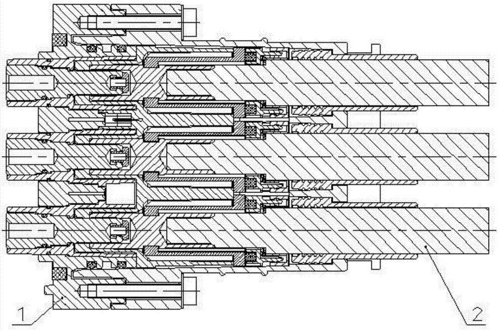
[0003] Aiming at the deficiencies of the prior art, the present invention proposes a wire-end inner core in a floating state in the wire-end shell to solve the wire-end female terminal and board-side male terminal due to manufacturing error or material deformation caused by single deviation when the wire-end female terminal is combined with the board-end male terminal. The cable sealing ring and the protective cover are installed in the front of the new energy vehicle electrical connector that is difficult to plug and unplug the terminal female terminal and the board terminal male terminal. The invention can also prevent the cable sealing ring from being easily removed from the wire end housing. It can avoid the friction between the cable and the inner hole of the wire end shell, avoid the cable from being worn out, and effectively protect the cable

Method used


Image

  • New energy vehicle electrical connector with integrally and front installed cable seal ring and protective sleeve
  • New energy vehicle electrical connector with integrally and front installed cable seal ring and protective sleeve
  • New energy vehicle electrical connector with integrally and front installed cable seal ring and protective sleeve

Examples


Embodiment Construction

[0021] The present invention will be further described below according to the accompanying drawings and in conjunction with the embodiments.

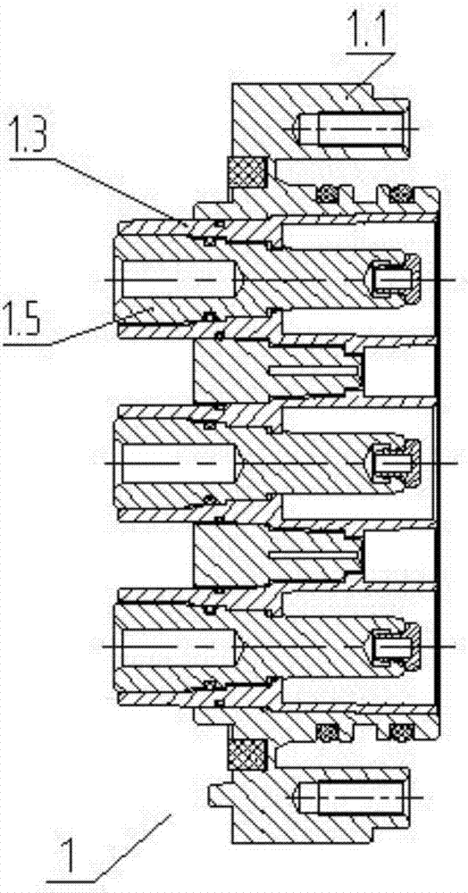
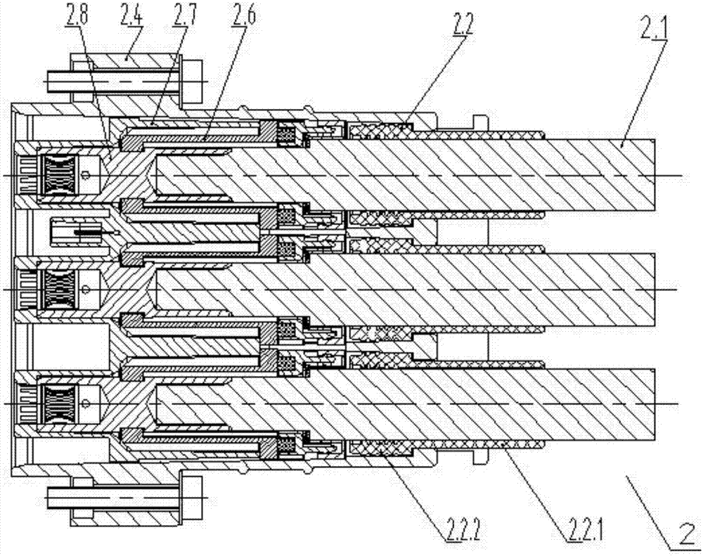
[0022] As shown in the attached figure, the new energy vehicle electrical connector with the cable sealing ring and the protective cover integrated in the front, including the board end 1 and the wire end 2; the board end 1 includes the board end shell 1.1, the board end inner core 1.3, and the board end male terminal 1.5; board end inner core 1.3 is inserted into the inner hole of board end shell 1.1; board end male terminal 1.5 is inserted into the inner hole of board end inner core 1.3; wire end 2 includes cable 2.1, cable sealing ring 2.2, wire end Shell 2.4, terminal jacket 2.6, wire end inner core 2.7, wire end female terminal 2.8; wire end female terminal 2.8 is inserted into the inner hole of wire end inner core 2.7 from the rear end of wire end inner core 2.7; terminal jacket 2.6 is a sleeve The front end of the terminal jacket...


PUM


Abstract

The invention discloses an electric connector for new energy automobiles in which a cable seal ring and a protective cover are integrally installed in front, including a board end and a wire end; the board end includes a board end shell, a board end inner core, and a board end male terminal; the board end The inner core is inserted into the inner hole of the board end shell; the board end male terminal is inserted into the inner hole of the board end inner core; the wire end includes cables, cable sealing rings, wire end shells, terminal jackets, wire end inner cores, Wire end female terminal; the inner core of the wire end is floating and inserted into the inner hole of the front end of the wire end housing; the further improvement is: the sealing ring and the protective sleeve of the cable sealing ring are integrated, and the sealing ring is placed on the wire end housing in front for cable insertion The inner hole shrinks in the inner hole; the rear end of the cable sealing ring protective sleeve protrudes from the inner hole hole on the wire end shell for the cable to enter. The invention can partially compensate the manufacturing or material deformation error of the wire end and the board end, solve the problems of difficulty in plugging and unplugging and unilateral wear caused by the unilateral combination of the female terminal of the wire end and the male terminal of the board end caused by this, and can avoid the cable The sealing ring is easy to fall off from the inner hole of the wire end housing, effectively protecting the cable.

Description

technical field [0001] The invention relates to the electrical field, in particular to a high-voltage electrical connector for a new energy vehicle. Background technique [0002] High-voltage electrical connectors for new energy vehicles, including board ends and wire ends, board ends include board end shells, board end inner cores, and board end male terminals. The terminal is inserted into the inner hole of the inner core of the board end. The wire end includes cables, cable sealing rings, wire end shells, terminal jackets, wire end inner cores, and wire end female terminals. The jacket is a sleeve-shaped component, which fits on the female terminal of the wire end, and the front end of the terminal jacket extends into the inner hole at the rear end of the inner core of the wire end. The inner core of the wire end is inserted into the inner hole of the front end of the wire end housing from the front end of the wire end housing, and the cable is inserted into the inner h...

Claims


Application Information

Patent Timeline
IPC IPC(8): H01R13/52H01R13/46B60R16/02
CPCH01R13/5202B60R16/02H01R13/46
Inventor 颜国兵
Owner SAIYANG ELECTROMECHANICAL
Learn More