Hidden type floor prevention system

A hidden, tank-body technology, applied in dikes, water conservancy projects, marine engineering, etc., can solve the problems of difficult operation, poor waterproof performance, heavy workload, etc., to improve the ability to withstand flood impact, prevent water seepage, The effect of preventing water seepage

Active Publication Date: 2017-11-10
STATE GRID CORP OF CHINA +1
View PDF7 Cites 7 Cited by
  • Summary
  • Abstract
  • Description
  • Claims
  • Application Information

AI Technical Summary

Problems solved by technology

The disadvantage of this structure is: the flood control baffle is a separate structure, and the waterproof performance is not good when used;
[0005] The disadvantages of the above two structures are: manual operation is required, not only the workload is heavy, but also the operation is more difficult when the rain is heavy

Method used


Image

  • Hidden type floor prevention system
  • Hidden type floor prevention system
  • Hidden type floor prevention system

Examples


Embodiment 1

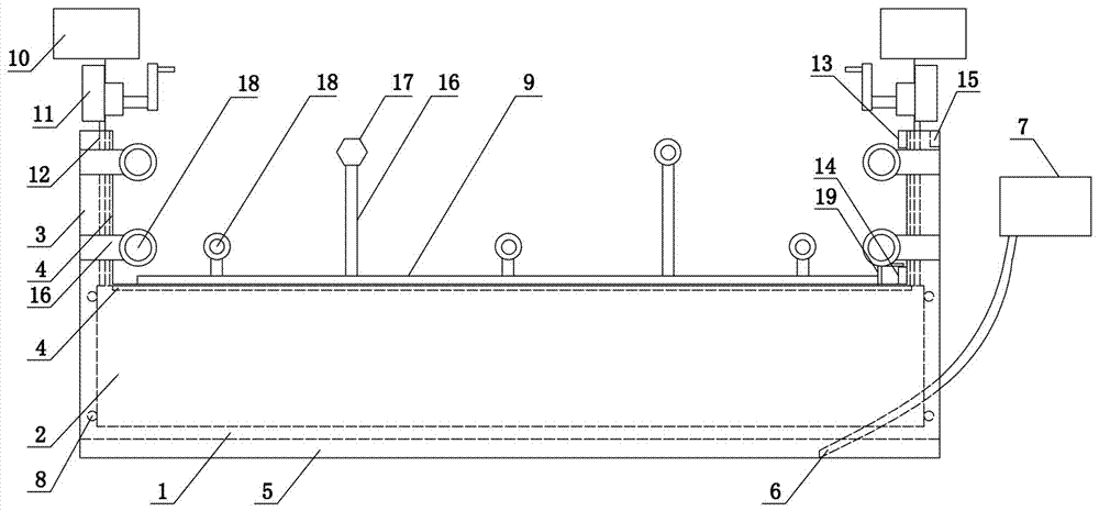
[0032] like figure 1 and figure 2 As shown, the present invention includes a main tank body 1, a water retaining plate 2, a power system and an auxiliary support structure, wherein guide rails 3 are arranged on the left and right sides of the main tank body 1, and bolts are passed through the notch of the main tank body 1 and the guide rails 3 The sealing gasket 4 is fixedly connected, and the drainage groove 5 is arranged under the main tank body 1, and the drainage groove 5 is connected with the main tank body 1, and the suction pipe 6 is arranged in the drainage groove 5, and the suction pipe 6 is connected with a water pump 7 and a water retaining plate 2 Located in the main tank body 1, guide wheels 8 matching the guide rail 3 are installed on the left and right sides of the water retaining plate 2, and the upper end of the water retaining plate 2 is welded with a protective plate 9 in the horizontal direction, and the width of the protective plate 9 is larger than that ...

Embodiment 2

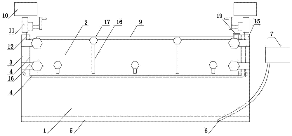
[0037]The present invention includes a main tank body 1, a water retaining plate 2, a power system and an auxiliary support structure, wherein guide rails 3 are arranged on the left and right sides of the main tank body 1, and the notch of the main tank body 1 and the inside of the guide rail 3 are fixedly connected and sealed by bolts Pad 4, a drain tank 5 is set under the main tank body 1, a water pump 6 is arranged in the drain tank 5, and the water pump 6 is connected to a water pump 7, the water retaining plate 2 is located in the main tank body 1, and the inner end surface of the water retaining plate 2 A plurality of rotating structures are arranged vertically. The rotating structure includes a rotating shaft 20 and a rotating plate 21 fixedly connected to the rotating shaft 20. The end of the rotating shaft 20 away from the rotating plate 21 is connected to the water baffle 2 in rotation. The left and right sides of the water baffle 2 are installed with guide rails. 3 M...

Embodiment 3

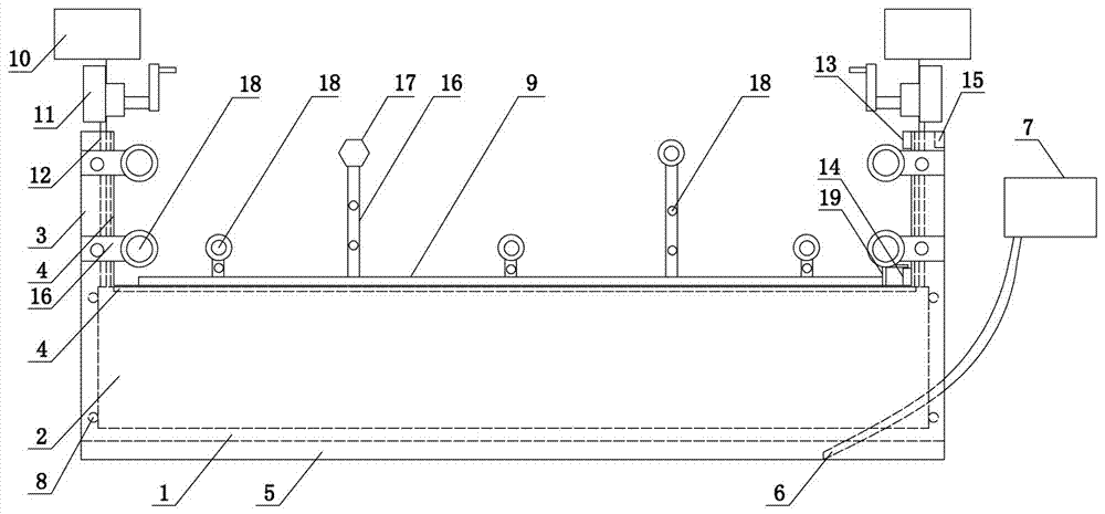
[0041] The structure of this embodiment is basically the same as that of Embodiment 1, the difference is: as Figure 4 As shown, a plurality of buffer springs 22 are arranged in the drainage tank 5, and when the water retaining plate 2 falls into the main tank body 1, it contacts with the buffer springs 22. This structure effectively reduces the pulling force of the protective plate 9 and the traction rope 12, especially In the case of failure of the traction rope 12, the buffer spring 22 can effectively prevent the parts of the present invention from being damaged by the impact force when the water retaining plate 2 is in free fall.


PUM


Abstract

The invention discloses a hidden type floor prevention system which comprises a main trough body (1), a water baffle (2), a power system and an auxiliary supporting structure, wherein guide rails (3) are arranged on the left and right sides of the main trough body (1); a water drainage slot (5) is formed in the lower portion of the main trough body (1); a horizontal protection plate (9) is arranged on the upper end surface of the water baffle (2); the power system comprises an electric hoist (10) and a manual winch (11); the auxiliary supporting structure comprises vertically arranged supporting rods (16) and horizontally arranged puller bolts (17); the supporting rods (16) are provided with threaded holes (18); and the puller bolts (17) penetrate through the threaded holes and then are in contact with the water baffle (2). By simultaneously arrangement of the electric hoist and the manual winch, the automation property of the hidden type floor prevention system is effectively improved; and furthermore, by additional arrangement of the auxiliary supporting device on the inner side of the water baffle, the flood prevention performance of the hidden type floor prevention system is effectively improved.

Description

technical field [0001] The invention belongs to the technical field of electric equipment protection, and in particular relates to a hidden flood prevention system. Background technique [0002] Due to the extremely precious land resources in the urban area and strict environmental requirements, especially in the core areas of large-scale cities with developed economies, it is becoming increasingly difficult to select substation sites. The site selection of substations is generally in flat areas, and the daily drainage is very small, even in rainy days. drain. However, with the increase of extreme natural disasters, especially the increase of extreme rainstorms, when encountering typhoons or heavy rains, due to excessive rainfall, it often happens that the water level outside the substation is the same as the water level inside the substation, and even the water level outside the substation is too high, resulting in The outside of the substation began to pour back into the ...

Claims


Application Information

Patent Timeline
Patent Type & Authority Applications(China)
IPC IPC(8): E02B3/10
CPCE02B3/102
Inventor 蒋坤田斌吴加新许东升方强华李晨于辉张路陈云斌高飞陈旭张大为
Owner STATE GRID CORP OF CHINA
Why Eureka
Try Eureka