Horizontal single-motor driving device for eyesight rectification overlapped lens group sliding

A single-motor-driven, vision-correcting technology, applied in installation, glasses/goggles, optics, etc., can solve problems such as cost increase, inability to achieve the purpose of the invention, and lack of provision

Active Publication Date: 2017-11-10
陈奎
View PDF9 Cites 7 Cited by
  • Summary
  • Abstract
  • Description
  • Claims
  • Application Information

AI Technical Summary

Problems solved by technology

The disadvantage is that one spectacles has only four arc rings with different curvatures, and the number of optional curvature mirrors for treating sick eyes is too small when wearing one such spectacles. It is very inconvenient to have spare glasses at home, which will affect the treatment; too many glasses for selection will increase the cost
[0007] (1) Unable to achieve the purpose of the invention: this patent only discloses the transmission mechanism, and does not disclose the structure of the "zoom lens", so it is not clear how the lens uses the transmission mechanism and how to achieve zooming. Spectacle lenses in 201310311306.4 "A New Orthokeratology Lens and Its Application Method", and 201521122053.7 "A Zoom Glasses" cannot realize the zoom application of "vision training";
[0008] (2) The transmission structure is wrong: the transmission order of the structure is motor-reduction gearbox-positive and negative screw-fixing bolt-front lens and rear lens slide in opposite directions
[0009] (3) The "fixing bolt" cannot realize the transmission: From the text and drawings of the patent document, it can be known that the "fixing bolt" is an intermediate component that transmits the "positive and negative screw" and the "lens", but the text and attached drawings of the patent document The figure does not provide the structure that the "fixing bolt" can drive the "positive and negative screw" and the "lens"
Only the positional relationship of each component, no structural relationship, can not achieve the transmission structure required to achieve the purpose of the invention

Method used


Image

  • Horizontal single-motor driving device for eyesight rectification overlapped lens group sliding
  • Horizontal single-motor driving device for eyesight rectification overlapped lens group sliding
  • Horizontal single-motor driving device for eyesight rectification overlapped lens group sliding

Examples


Embodiment 1

[0045] Embodiment 1. Horizontal single-motor drive device for sliding of overlapping double-lens groups for vision correction

[0046] Such as figure 1 , 2 , 3, 4,

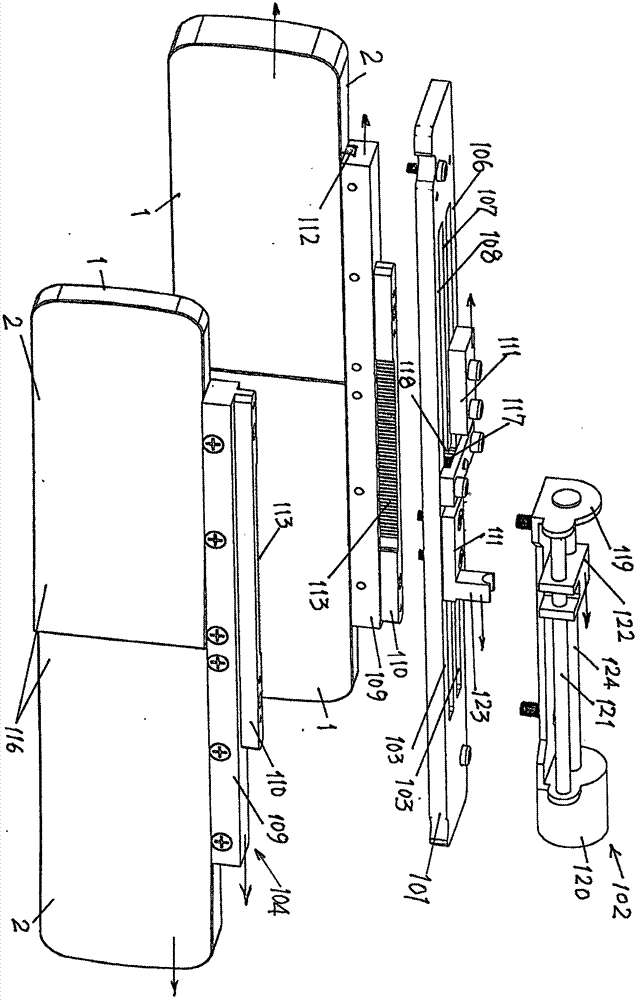
[0047] 1. A horizontal single-motor drive device for sliding overlapping double-lens groups for vision correction, which is characterized in that it includes a double-hole strip plate 101 fixed on an “L”-shaped bracket plate 119 at one end of the double-hole strip plate 101 The deceleration motor assembly 102 is provided with two lens assemblies 104 that are slidingly connected in the two strip holes 103 of the double-hole strip plate 101;

[0048] The structure of the double-hole strip plate 101: a strip plate is provided with two parallel strip holes 103, and the strip hole 103 divides the strip plate into an outer plate 106, a middle partition plate 107, and an inner plate 108; The upper center of the middle partition 107 is provided with a middle partition depression or a middle partition hole 118;

[0049...

Embodiment 2

[0069] Embodiment 2. Horizontal single-motor drive device for sliding of overlapping double-lens groups for vision correction

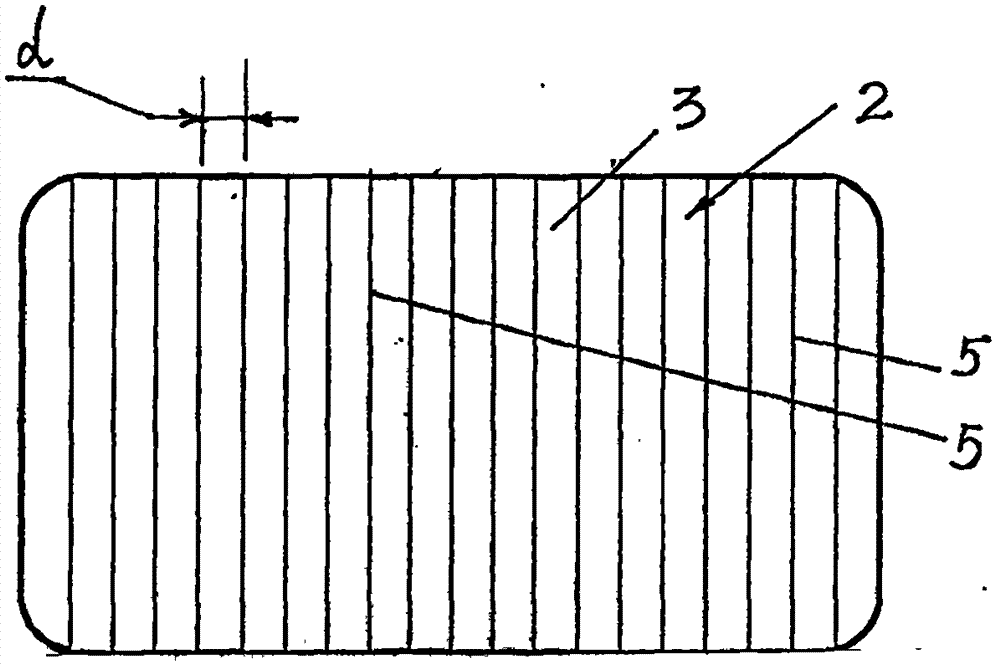
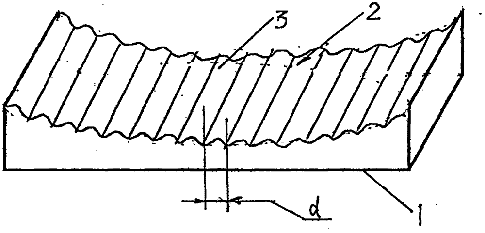
[0070] Such as figure 1 , 2 , 3, 4, according to the structure of the above-mentioned embodiment 1, only the entire equidistant width strip curved surface 3 of the lens is different, and all the equidistant width strip curved surfaces 3 of a plurality of vertical equidistant zoom stripe surfaces 2 are arranged side by side As follows, a plurality of vertical equidistant zoom fringe surfaces 2 and all equidistant width strip curved surfaces 3 have the same diopter difference N, and the specific arrangement and distribution of lenses with diopter values ​​ranging from 200 degrees to -800 is as follows:

[0071]

[0072] In the above table: ordinal numbers refer to: 1 to 41 refer to the serial numbers of a total of 41 equidistant width strip surfaces 3;

[0073] Diopter refers to: the diopter value of the lens on the equidistant width strip surface ...


PUM


Abstract

The invention provides a horizontal single-motor driving device for eyesight rectification overlapped lens group sliding, belonging to a device electrically driving the two groups of parallel optical lenses to perform slidable focal length variation eyesight rectification. The horizontal single-motor driving device includes a deceleration motor assembly fixed on an L-shaped support plate at one end on a double-hole strip-shaped plate, two slidable lens assemblies are respectively arranged in the two strip-shaped holes of the double-hole strip-shaped plate, each lens assembly includes lenses with multiple vertical equidistant focal length variation striped surfaces, a grooved strip connecting the lenses, a slide substrate, a top clamp plate that are connected successively and mutually from the bottom to the top, the two lenses with multiple vertical equidistant focal length variation striped surfaces connected in the grooved strip form a double-lens group, the deceleration motor enable the two lens assemblies to slide in the opposite directions through the engaging gears at the two sides, and the overlapped two lenses generate a lot of combined diopter. A motor is additionally provided with a gear, so that the two double-lens groups can be driven to perform the constant speed movement in the opposite directions at the constant speed. The focal length variation training device is helpful in storing myopia vision.

Description

technical field [0001] The invention belongs to the technical field of zoom optical lenses, and in particular relates to a sliding motor drive device for sliding two sets of parallel optical lenses to drive two groups of parallel optical lenses to zoom in and out for vision correction. Background technique [0002] Chinese patent 201610092191.8 "A Gradient Focus Lens" provides a lens with a flat bottom surface and a free-form surface on the other side, the free-form surface is composed of concave surfaces, and several regions are provided on the free-form surface, and each region are equal in vertical length. The length of the area is 0.1.0 mm to 100 mm, the diopters of the area are 1 to 2000 degrees, the diopters are evenly distributed on the lens, and the focal points are equally divided into each unit length. [0003] The defect of the above-mentioned "A Gradient Focus Lens" is that the "free-form surface" is used as a training lens for correcting myopia. It is difficult...

Claims


Application Information

Patent Timeline
Patent Type & Authority Applications(China)
IPC IPC(8): G02B7/02G02C7/02
CPCG02B7/021G02B7/023G02B7/04G02C7/02G02C7/063G02C7/08G02C7/088
Inventor 陈奎
Owner 陈奎
Why Eureka
Try Eureka