Firm electrical connection power supply equipment

A power supply equipment and power technology, applied in the field of electric power, can solve the problems of inability to power supply by electrical components, loose plugging, potential safety hazards, etc., to improve the accuracy of plugging, the speed of plugging, the stability of plugging, and the prevention of electric shock. effect of accident

Inactive Publication Date: 2017-11-10
陆佳浩
View PDF3 Cites 9 Cited by
  • Summary
  • Abstract
  • Description
  • Claims
  • Application Information

AI Technical Summary

Problems solved by technology

[0002] The power supply device is an important part of power equipment. It is mainly composed of a plug and a socket, and the power supply connection is realized by plugging. Although the plug-in power supply method in the prior art is simple and fast, it is extremely easy to be dragged. Pulling, pulling and other external factors lead to loose plugging, and the electrical components cannot be plugged in and powered normally, which has great disadvantages. There is a greater potential safety hazard in the danger of electric shock

Method used


Image

  • Firm electrical connection power supply equipment
  • Firm electrical connection power supply equipment
  • Firm electrical connection power supply equipment

Examples


Embodiment Construction

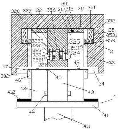
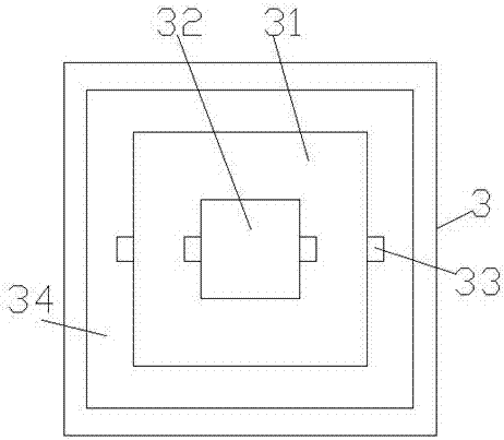
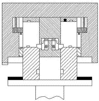
[0020] Such as Figure 1-Figure 6 As shown, a firm electric power supply device of the present invention includes a socket part 3 and a plug part 4 mated with the socket part 3, the socket part 3 is provided with a cavity 31, and the cavity The inner walls of the left and right sides of the chamber 31 are correspondingly provided with a first sliding groove 33, and the top of the first sliding groove 33 is provided with a second sliding groove 35 on the side away from the cavity 31. The slot 35 is provided with a sliding block 353 and a guide bar 351 that is slidingly fitted and connected with the sliding block 353, and the inner end of the sliding block 353 penetrates into the first sliding slot 33 and is slidingly fitted. , the bottom of the sliding block 353 in the first sliding groove 33 is provided with a clamping member 3532, and the inner top wall of the cavity 31 is provided with a downwardly extending insertion rod 32, and the insertion rod 32 is provided with left a...


PUM


Abstract

The invention discloses firm electrical connection power supply equipment. The firm electrical connection power supply equipment comprises a socket part and a plug part, wherein the plug part is plugged into the socket part in a matching way, an accommodating cavity is formed in the socket part, first sliding grooves are correspondingly formed in inner walls of a left side and a right side of the accommodating cavity, a second sliding groove is formed in one side, deviating from the accommodating cavity, of a top part of each first sliding groove, sliding blocks and moving guide rods are arranged in the second sliding grooves, the moving guide rods are connected with the sliding blocks in a sliding and matching way, inner ends of the sliding blocks penetrate through the first sliding grooves and are matched with the first sliding grooves in a sliding way, clamping pieces are arranged at bottom parts of the sliding blocks in the first sliding grooves, a plug rod is arranged at a top wall of the accommodating cavity and extends downwards, cavities corresponding to each other in a left-right way are formed in a lower part of the plug rod, a baffle block is arranged in the cavities in a left side and a right side, a third sliding groove is formed in a top part of each cavity, and push blocks are arranged in the cavities. The firm electrical connection power supply equipment is simple in structure and firm in connection, and has functions electric shock prevention and loosing prevention, and the safety and the stability during power supply are improved.

Description

technical field [0001] The invention relates to the technical field of electric power, in particular to a firm electric plug-in power supply device. Background technique [0002] The power supply device is an important part of power equipment. It is mainly composed of a plug and a socket, and the power supply connection is realized by plugging. Although the plug-in power supply method in the prior art is simple and fast, it is extremely easy to be dragged. Pulling, pulling and other external factors lead to loose plugging, and the electrical components cannot be plugged in and powered normally, which has great disadvantages. The risk of electric shock is a great safety hazard. Contents of the invention [0003] The technical problem to be solved by the present invention is to provide a firm electric plug-in power supply device, which can solve the above-mentioned problems in the prior art. [0004] The present invention is achieved through the following technical solutio...

Claims


Application Information

Patent Timeline
Patent Type & Authority Applications(China)
IPC IPC(8): H01R13/02H01R13/502H01R13/627H01R13/629H01R13/631H01R13/635
CPCH01R13/629H01R13/02H01R13/502H01R13/6278H01R13/631H01R13/635
Inventor 陆佳浩
Owner 陆佳浩
Why Eureka
Try Eureka