Gas extraction drill hole plugging method and device

A gas extraction and plugging device technology, applied in gas discharge, safety devices, mining equipment and other directions, can solve the problems of waste grouting pipe, difficult transportation of viscous slurry, failure of sealing holes, etc., to achieve strong adaptability and reliability. Good sealing and expansion performance

Inactive Publication Date: 2015-01-14
NORTH CHINA INST OF SCI & TECH
View PDF6 Cites 10 Cited by
  • Summary
  • Abstract
  • Description
  • Claims
  • Application Information

AI Technical Summary

Problems solved by technology

Compared with other methods, the method of wrapping polyurethane A and B bags on the gas drainage pipe is relatively simple, but this method is mixed outside the gas drainage borehole, because the reaction time of polyurethane A and B is relatively fast ( Only a few minutes), so when sealing the innermost end of the gas drainage borehole, it is often because the polyurethane material A and material B have reacted when the delivery is not in place, resulting in hole sealing failure
Injection of polyurethane outside the borehole also includes two situations. One is to use compressed air or a grouting pump to send the mixed polyurethane material A and B outside the borehole to the sealing position inside the borehole through a grout delivery pipe. , but it has requirements on the grouting time (injection within 5 minutes), and the mixed viscous grout is difficult to transport for a long distance in the grouting pipe; the other is to separate the polyurethane through two grouting pipes outside the borehole Material A and material B are sent to the inner end of the borehole for mixed reaction, which not only wastes a grouting pipe, but also has the problem that the viscous grout of material A and material B is difficult to transport for a long distance in the grouting pipe

Method used


Image

  • Gas extraction drill hole plugging method and device
  • Gas extraction drill hole plugging method and device

Examples


Embodiment Construction

[0012] The present invention will be described in detail below in conjunction with the accompanying drawings and embodiments.

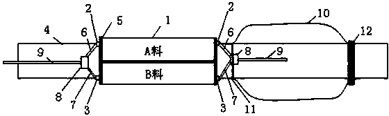
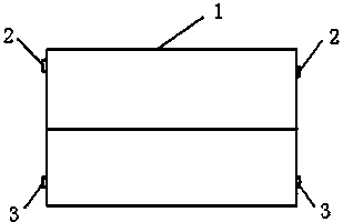
[0013] Such as figure 1 , figure 2 As shown, the plugging device of the present invention includes a soft bag 1, in which polyurethane material A and material B are isolated, and the two sides of the material A and material B of the soft bag 1 are respectively provided with a hole-sealing bag joint 2 , 3. The two ends of soft bag 1 are wound on the outer wall of gas extraction pipe 4, and it is fixed with adhesive tape 5 (the connection position is also fixed in the figure). Connect a nylon tube 6, 7 to the sealing bag joints 2, 3 on both sides of material A and material B respectively, and connect the two nylon tubes 6, 7 on the same side to one interface of the same tee 8, The third interface of each tee 8 is connected with an air pipe 9 . Put the ventilation pipe 9 on one side into an elastic bag 10, then wrap the elastic bag 10 on the outer w...


PUM


Abstract

The invention relates to a gas extraction drill hole plugging method and device. The gas extraction drill hole plugging method includes steps of 1) setting at least one plugging device, wherein each plugging device comprises a soft bag filled with polyurethane A and B which are isolated, two sides of the A and the B are connected with two vent pipes via tee joints respectively, and one of the vent pipes is placed in an elastic bag; 2) respectively winding and fixing the soft bag and the elastic bag on a gas extraction pipe inserted into an extraction drill hole, and the vent pipe on the outer side of the extraction drill hole is connected with a pressure gas source; 3) starting the pressure gas source, wherein pressure gas enters the vent pipes to extrude the A and the B into the elastic bag, and the A and the B are mixed to form thick size and are expanded in the elastic bag to plug the drill hole. The gas extraction drill hole plugging device is simple in structure, convenient to use and widely applicable to plugging of various gas drill holes.

Description

technical field [0001] The invention relates to a method and a device for plugging a borehole, in particular to a method and a device for plugging a gas drainage borehole. Background technique [0002] Gas drainage is a fundamental measure to control coal mine gas, and its drainage effect is affected by many factors, among which the quality of sealing holes is the most critical factor. At present, the most commonly used method for gas drainage borehole plugging is "two plugging and one injection" pressure sealing, which is to use air bags, water injection capsules, grouting capsules, winding polyurethane or drilling at both ends of the gas drainage borehole. The polyurethane is injected externally to form a plug, and then the sealing material is injected under pressure between the two plugs, thereby sealing the annular space between the gas extraction pipe and the borehole wall and the cracks around the borehole wall. [0003] However, the pressure of the airbag sealing dev...

Claims


Application Information

Patent Timeline
Patent Type & Authority Applications(China)
IPC IPC(8): E21B33/13E21F7/00
CPCE21B33/13E21F7/00
Inventor 陈学习
Owner NORTH CHINA INST OF SCI & TECH
Why Eureka
Try Eureka