Connecting structure of plug-in pipe fitting

A connection structure and plug-in technology, which is applied in the direction of mechanical equipment, couplings, etc., can solve the problems that the plug-in connection method cannot be applied, and achieve the effect of simple structure, preventing loose connection of pipelines, and convenient connection assembly and disassembly

Inactive Publication Date: 2014-05-14
MACRO THERMAL ENERGY TECH
View PDF9 Cites 9 Cited by
  • Summary
  • Abstract
  • Description
  • Claims
  • Application Information

AI Technical Summary

Problems solved by technology

However, this plug-in connection method is only applicable to the situation where the position of the single pipe is not fixed, or only one end of the pipeline is plugged in; When both are plug-in connections, because the total length of the insertion tube is often greater than the distance between the two ends of the connection, the existing insertion connection method cannot be applied.
Simultaneously, existing this plug-in connection also does not solve the problem of inconvenient dismounting

Method used


Image

  • Connecting structure of plug-in pipe fitting
  • Connecting structure of plug-in pipe fitting
  • Connecting structure of plug-in pipe fitting

Examples


Embodiment 1

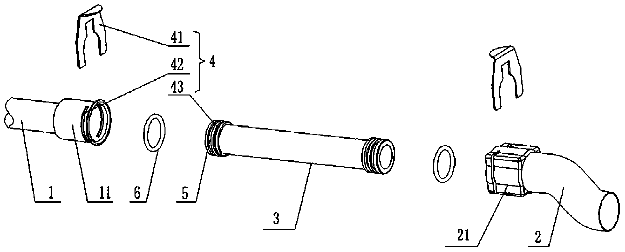
[0031] Such as figure 1 As shown, a connection structure of plug-in pipe fittings includes: end pipe 1 and end pipe 2 with fixed positions, and plug-in pipe fitting 3 connecting end pipe 1 and end pipe 2 .

[0032] Wherein, the two ends of the plug-in pipe fitting 3 are inserted on the end pipe 1 and the end pipe 2 respectively, and a movable socket with adjustable relative displacement is formed between the plug-in pipe fitting 3 and the end pipe 1 . In order to achieve position locking between the plug-in pipe fitting 3 and the end pipe 1, a buckle mechanism 4 for limiting relative displacement is also provided on the plug-in pipe fitting 3 and the end pipe 1 . In order to achieve position locking between the plug-in pipe fitting 3 and the end pipe 2, a buckle mechanism for limiting relative displacement is also provided on the plug-in pipe fitting 3 and the end pipe 2. In this embodiment, the movable socket refers to: a connector 11 is integrally formed on the end pipe 1, ...

Embodiment approach

[0033] The buckle mechanism 4 includes: an inserting plate 41 , a slot 42 penetrating through the shell wall of the connector 11 , and a slot 43 corresponding to the slot 42 provided on the plug-in pipe 3 . The inserting plate 41 is inserted into the slot 43 through the slot 42 to realize position locking between the plug-in pipe 3 and the end pipe 1 . In this embodiment, it is preferable that the slots 43 are symmetrical to each other, and there is preferably a U-shaped opening on the inserting plate 41 , and the U-shaped opening is inserted into the two left and right slots to fix the plug-in pipe 3 . In this way, the plug board 41 is very stable and reliable when plugged in. In other embodiments, the slot is only a slot, or the plug-in plate is replaced by a snap ring that extends into the connector through the slot. When the snap ring snaps into the slot, the plug-in pipe and Position locking between end tubes. As another equivalent implementation manner of the buckle me...

Embodiment 2

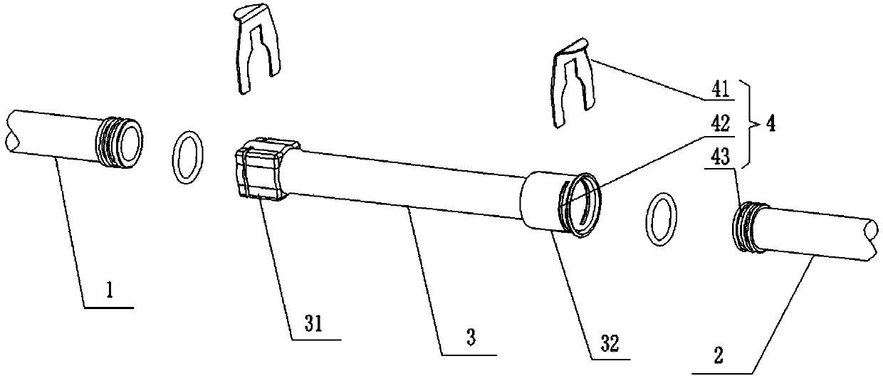
[0037] Such as figure 2 As shown, a connection structure of plug-in pipe fittings includes: end pipe 1 and end pipe 2 with fixed positions, and plug-in pipe fitting 3 connecting end pipe 1 and end pipe 2 . Wherein, the two ends of the plug-in pipe 3 are inserted on the end pipe 1 and the end pipe 2 respectively, and form a movable socket with adjustable relative displacement with at least one of the end pipe 1 and the end pipe 2 . In order to realize the position locking between the plug-in pipe 3 and the end pipe, a buckle mechanism 4 for limiting relative displacement is provided between the plug-in pipe 3 and the end pipe.

[0038] The connection structure of a plug-in pipe provided in this embodiment is basically the same as that of Embodiment 1, the difference is that:

[0039] The flexible socket refers to: the two ends of the plug-in pipe 3 are provided with a connector 31 and a connector 32, and the end pipe 1 and the end pipe 2 are respectively inserted into the con...


PUM


Abstract

The invention discloses a connecting structure of a plug-in pipe fitting. The connecting structure comprises two fixed end pipes and the plug-in pipe fitting for connecting the two end pipes and is characterized in that the two ends of the plug-in pipe fitting are inserted to the two end pipes respectively, movable sleeve connection with the adjustable relative displacement is formed between the plug-in pipe fitting and at least one end pipe, and a buckling mechanism for limiting the relative displacement is arranged between the plug-in pipe fitting and the corresponding end pipe. Compared with the prior art, the connecting structure of the plug-in pipe solves the problem that the two ends of a hard pipe cannot be connected in a plug-in mode, ensures connection reliability, and effectively prevents pipeline connection loosening caused by transportation vibration.

Description

technical field [0001] The invention relates to the technical field of connection of rigid pipe fittings, in particular to a connection structure of plug-in pipe fittings. Background technique [0002] At present, there are mainly two methods of threaded connection or welding for the connection of hard pipe fittings. As far as the threaded connection is concerned, during transportation, the hard pipe connector is prone to loosening after being subjected to long-term vibration, resulting in water leakage from the connector. As far as welding is concerned, although it can effectively avoid loosening and falling off caused by vibration, once the pipes are welded, it is difficult to disassemble, and the welded joints are easily corroded and rusted. [0003] In order to avoid the problems of loosening and easy corrosion, in the prior art, the connection and fixation between adjacent hard pipes is also realized by plug-in clamping. For example, a Chinese patent with a notificati...

Claims


Application Information

Patent Timeline
Patent Type & Authority Applications(China)
IPC IPC(8): F16L37/12
CPCF16L37/144
Inventor 余少言史玉军王克军陈耀华张永明
Owner MACRO THERMAL ENERGY TECH
Why Eureka
Try Eureka