Wireless power transmission device

A technology of wireless energy transmission and electric energy, applied in the direction of circuit devices, circuits, inductors, etc., can solve the problems of increasing EMC conduction interference, increasing common mode current, increasing EMC radiation interference, etc., to improve energy transmission efficiency and reduce circulating current Effect

Inactive Publication Date: 2017-11-14
NINGBO WEIE ELECTRONICS TECH CO LTD
View PDF8 Cites 4 Cited by
  • Summary
  • Abstract
  • Description
  • Claims
  • Application Information

AI Technical Summary

Problems solved by technology

like figure 2 As shown, the high-frequency AC voltage on the coil is more likely to form a common-mode current to the ground through this parasitic capacitance, which increases EMC conduction interference
Moreover, when the size of the transmitting coil increases, the circumference of the coil will increase accordingly. If a high-frequency alternating current flows through the coil, then the high-frequency current is more likely to form electromagnetic waves to radiate out, increasing EMC radiation interference
[0004] Another way is to increase the magnetic field of the transmitting coil by increasing the alternating current in the transmitting coil, which will increase the voltage across the transmitting coil (V=jωLs·Is), requiring a resonant capacitor Cs with a greater withstand voltage value Resonates with the transmitting coil Ls at the system operating frequency point, and after the voltage of the transmitting coil increases, according to the calculation formula of the common mode current above, the common mode current to the ground will also increase

Method used


Image

  • Wireless power transmission device
  • Wireless power transmission device
  • Wireless power transmission device

Examples


Embodiment Construction

[0045] Some preferred embodiments of the present invention will be described in detail below with reference to the accompanying drawings, but the present invention is not limited thereto.

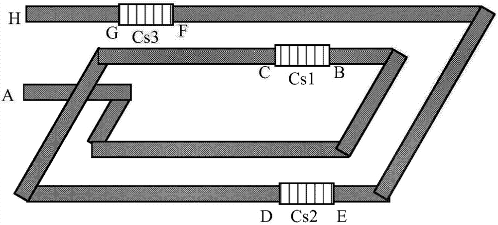
[0046] refer to image 3 Shown is a schematic diagram of the power transmission coil part in the wireless power transmission device according to the present invention, and the power transmission coil part includes an inverter circuit ( image 3 not shown), the inverter circuit is used to convert the external DC voltage signal into an AC voltage signal for output, and the AC voltage signal is transmitted to the power transmitting coil.

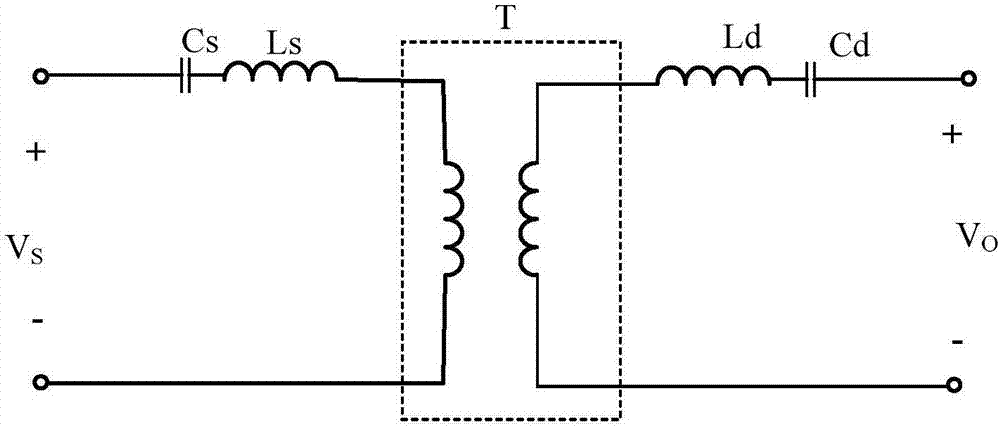
[0047] The power transmission coil part also includes a power transmission coil and a primary side compensation capacitor, and the primary side compensation capacitor is used to compensate the inductance of the power transmission coil, so that the resonance of the power transmission coil and the primary side compensation capacitor The frequency is consisten...


PUM


Abstract

The invention discloses a wireless power transmission device. According to the wireless power transmission device, a primary side compensation capacitor (or a secondary side compensation capacitor) is configured to comprise N sub-compensation capacitors which are evenly connected in a power transmitting coil (or a power receiving coil), so as to divide the power transmitting coil (or the power receiving coil) into N equal parts accordingly. By adopting the connection structure of the distributed capacitors, a voltage of each section of the power transmitting coil (or the power receiving coil) can be reduced, thus a common mode current of the power transmitting coil to the ground or a circular current of the power receiving coil to metal is reduced, and the resonant frequencies of the coil and the total compensation capacitors of a primary side or a secondary side are identical with the operating frequency of the system, thereby ensuring the highest energy transmission efficiency.

Description

technical field [0001] The present invention relates to the field of wireless power transmission, and more specifically, to a wireless power transmission device. Background technique [0002] The magnetic resonance wireless charging system includes a power transmitter and a power receiver, such as figure 1 As shown, the power transmitter receives external power to generate a spatial magnetic field to wirelessly transmit the energy to the power receiver. [0003] In order to enable the power receiving end to induce a spatial magnetic field in a wider range to generate voltage for electronic equipment, one way is to increase the size and inductance of the transmitting coil in the power transmitting end, but increase the size and inductance of the transmitting coil, It is often necessary to increase the number of turns and area of ​​the transmitting coil, and according to the calculation formula of capacitance, C=εS / D, increasing the coil area will increase the parasitic capac...

Claims


Application Information

Patent Timeline
IPC IPC(8): H02J50/12H01F38/14
CPCH01F38/14
Inventor 车丙晨
Owner NINGBO WEIE ELECTRONICS TECH CO LTD
Why Eureka
Try Eureka