Automatic mechanical arm

A technology of manipulators and manipulators, applied in the direction of manipulators, program-controlled manipulators, feeding devices, etc., can solve the problems of relying on manual loading and unloading, and the inability to realize mechanized production, so as to improve efficiency, flexibility and safety, and overcome single application Effect

Inactive Publication Date: 2017-11-17
FOSHAN IROBOT AUTOMATIC
View PDF7 Cites 10 Cited by
  • Summary
  • Abstract
  • Description
  • Claims
  • Application Information

AI Technical Summary

Problems solved by technology

[0004] The purpose of the present invention is to provide an automatic manipulator, which is a double-arm rotary pendulum loading and unloading manipulator used in the hardware processing process, so as to solve the problem that the existing single-process stamping production can only rely on manual loading and unloading. The problem of mechanized production

Method used


Image

  • Automatic mechanical arm

Examples


Embodiment 1

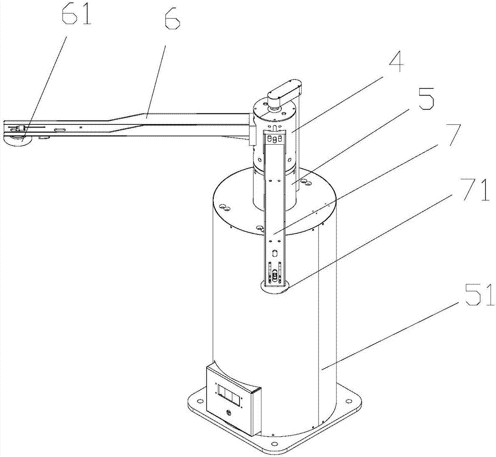
[0027] In this automatic manipulator embodiment scheme, such as figure 1 As shown, the angle between the first mechanical arm 7 and the second mechanical arm 6 is 90°, and its working principle is as follows:

[0028] Manually place the workpiece to be processed on the loading table, and the system detects that there is material, and the double-sheet mechanism divides the workpiece into sheets, and is checked by the double-sheet detection system to ensure that it is a single-sheet workpiece.

[0029] The rotating shaft 4 drives the first robot arm 7 and the second robot arm 6 to rotate 45°, and the first robot claw 71 is placed above the discharge position of the feeding table while the second robot claw 61 is placed above the mold of the C-type machine tool.

[0030] The lifting shaft 5 drives the rotating shaft 4 and the first mechanical arm 7 and the second mechanical arm 6 to move downward, the first mechanical claw 71 grabs the workpiece to be processed on the loading tab...

Embodiment 2

[0036] Another embodiment of the automatic manipulator is also provided in the present invention. The main difference between it and the previous embodiment is that the angle between the two mechanical arms is 120°, and its working principle is as follows:

[0037] After the on-line positioning device adjusts and positions the workpiece on the conveyor belt, the turning mechanism grabs the workpiece and transfers it to the positioning mechanism.

[0038] The rotating shaft 4 drives the first mechanical arm 7 and the second mechanical arm 6 to rotate 60°, and the first mechanical claw 71 is placed above the positioning mechanism while the second mechanical claw 61 is placed above the die of the stamping equipment.

[0039] The lifting shaft 5 drives the rotating shaft 4, the first mechanical arm 7 and the second mechanical arm 6 to move downward, the first mechanical claw 71 grabs the workpiece to be processed on the positioning mechanism, and the second mechanical claw 61 grabs t...


PUM


Abstract

The invention discloses an automatic mechanical arm. The automatic mechanical arm comprises a rotating shaft, a lifting shaft, a lifting shaft body, a first mechanical arm, a second mechanical arm, a first mechanical paw and a second mechanical paw, wherein the first mechanical paw is installed on one end of the first mechanical arm; the second mechanical paw is installed on one end of the second mechanical arm; the other end of the first mechanical arm and the other end of the second mechanical arm are installed on the rotating shaft; an angle is formed between the first mechanical arm and the second mechanical arm; the lifting shaft is installed on the lifting shaft body; the rotating shaft is installed at the top end of the lifting shaft; the lifting shaft and the rotating shaft are driven by different motors, so that the rotating shaft vertically moves along with the lifting shaft, and the first mechanical arm and the second mechanical arm rotate along with the rotating shaft. According to the automatic mechanical arm, feeding and discharging can be carried out at the same time, the automatic mechanical arm can adapt to complex and changeable workpiece positions, automatic material taking and feeding are realized, and the problems that an existing device is single in application, low in efficiency and easy to cause accidents are solved.

Description

technical field [0001] The invention relates to the field of automatic production equipment, in particular to an automatic manipulator, which is a double-arm rotary swing loading and unloading manipulator used in hardware processing procedures. Background technique [0002] At present, the loading and unloading manipulators specially suitable for single-process stamping in the hardware processing process market are relatively simple, and the mechanical arms are all single arms, which is relatively inefficient for the hardware processing industry with fast production requirements. However, the existing relatively mature loading and unloading manipulators are suitable for multi-stations in the whole line, and are not suitable for single-process stamping production and the cost is relatively high. Therefore, the existing single-process stamping mainly adopts the method of manual material taking, loading, and discharging. This production method not only has a high dependence on ...

Claims


Application Information

Patent Timeline
Patent Type & Authority Applications(China)
IPC IPC(8): B21D43/10B21D45/06B25J9/12
CPCB21D43/105B21D45/06B25J9/0087B25J9/123Y02P70/10
Inventor 潘扬树
Owner FOSHAN IROBOT AUTOMATIC
Why Eureka
Try Eureka