A Numerical Method for Obtaining Coupling Loss Factor

A technology of coupling loss and numerical method, applied in the field of high frequency dynamic response prediction, can solve problems such as high cost, only applicable theoretical methods, long design cycle, etc., and achieve the effect of accurate calculation

Active Publication Date: 2018-04-24
SOUTHEAST UNIV
View PDF4 Cites 0 Cited by
  • Summary
  • Abstract
  • Description
  • Claims
  • Application Information

AI Technical Summary

Problems solved by technology

Among them, the test method can obtain reliable results, but the cost of carrying out test analysis is high and the design cycle is long; the theoretical method is only suitable for simple systems, and it is difficult to solve the problem of dynamic response prediction of complex systems; numerical methods are well applicable to complex systems It is an effective auxiliary means for experimental analysis

Method used


Image

  • A Numerical Method for Obtaining Coupling Loss Factor
  • A Numerical Method for Obtaining Coupling Loss Factor
  • A Numerical Method for Obtaining Coupling Loss Factor

Examples


Embodiment Construction

[0045] The present invention will be further described below in conjunction with the accompanying drawings.

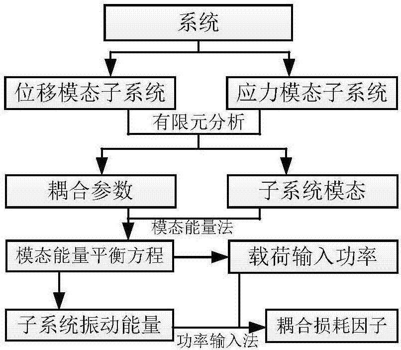
[0046] Such as figure 1 Shown is the principle flow chart of the present invention, mainly comprises the following steps:

[0047] Step (1) divides the system into continuously coupled subsystems:

[0048] Divide the system into continuous coupling subsystems with imaginary interfaces, and approximate the boundary conditions of the subsystems on the coupling interface, assuming that the more "rigid" subsystem is a free boundary on the coupling interface, and assuming the "softer" subsystem Fixed support on the coupling interface. The vibration of adjacent subsystems is described by displacement mode and stress / acoustic pressure mode, respectively.

[0049] Step (2) Calculate the mode of the subsystem:

[0050] The modal parameters of the subsystems are calculated based on the finite element method.

[0051] Step (3) Calculate the coupling parameters between modes ...


PUM


Abstract

Disclosed is a numerical method for obtaining a coupling loss factor, the method comprising the following steps: (1) dividing a system into continuously coupled sub-systems; (2) calculating modes of each sub-system; (3) calculating coupling parameters between the modes in a neighboring sub-system; (4) calculating, on the basis of a modal energy method, the distribution of a load input power and the distribution of a modal vibration energy of a mode in a frequency domain; (5) calculating and analyzing in a frequency band the total input power of the loads of each sub-system and the total vibration energy of each sub-system; (6) calculating, on the basis of a power input method, a coupling loss factor. The method for obtaining a coupling loss factor is derived from statistical energy theory. The numerical method obtains a coupling loss factor on the basis of the modal energy method and the power input method, combining the modal energy method with the power input method to enable consideration of the impact of power transmissions between non-resonant modes. Thus, the method accurately calculates coupling loss factors between sub-systems in the statistical energy method.

Description

technical field [0001] The invention relates to the technical field of high-frequency dynamic response prediction based on a statistical energy method, in particular to a numerical method for obtaining coupling loss factors. Background technique [0002] During the mission cycle, the spacecraft faces severe high-intensity, broadband noise and other environments, which may cause structural failure or failure of precision instruments and instruments. Therefore, in the design process of the spacecraft, the influence of high-intensity, broadband noise needs to be considered. Experimental methods, theoretical methods and numerical methods can be used to predict the dynamic response of the system under high-frequency noise excitation. Among them, the test method can obtain reliable results, but the cost of carrying out test analysis is high and the design cycle is long; the theoretical method is only suitable for simple systems, and it is difficult to solve the problem of dynamic...

Claims


Application Information

Patent Timeline
Patent Type & Authority Patents(China)
IPC IPC(8): G06F17/50
CPCG06F30/23
Inventor 李彦斌张鹏费庆国吴邵庆杨轩姜东
Owner SOUTHEAST UNIV
Why Eureka
Try Eureka