
Electronic lock

An electronic lock and electronic technology, applied in the field of electronic locks, can solve problems such as affecting use and single function, and achieve the effect of improving service life, improving functionality and convenient use.

Inactive Publication Date: 2017-11-24
GUANGZHOU DANJUE COMM TECH CO LTD
View PDF1 Cites 1 Cited by
  • Summary
  • Abstract
  • Description
  • Claims
  • Application Information

AI Technical Summary

Problems solved by technology

[0004] In view of the deficiencies in the existing technology, the purpose of the present invention is to provide an electronic lock to solve the problem that the existing technology cannot be controlled by voice recognition, and the function is single, which affects the use

Method used


Image

  • Electronic lock
  • Electronic lock

Examples


Embodiment Construction

[0017] In order to make the technical means, creative features, goals and effects achieved by the present invention easy to understand, the present invention will be further described below in conjunction with specific embodiments.

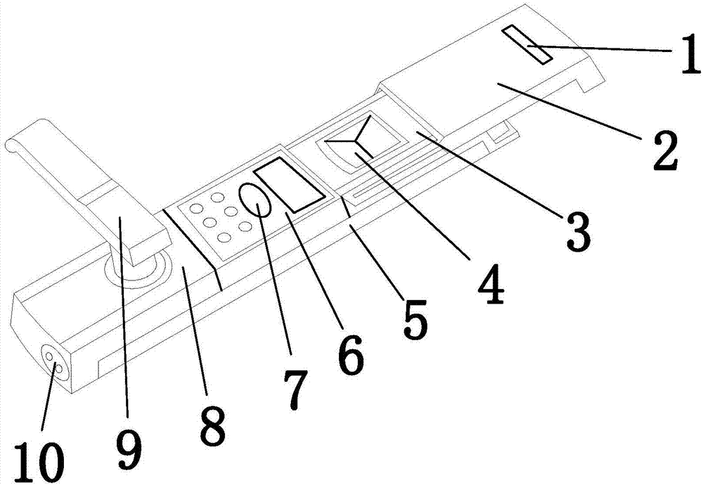
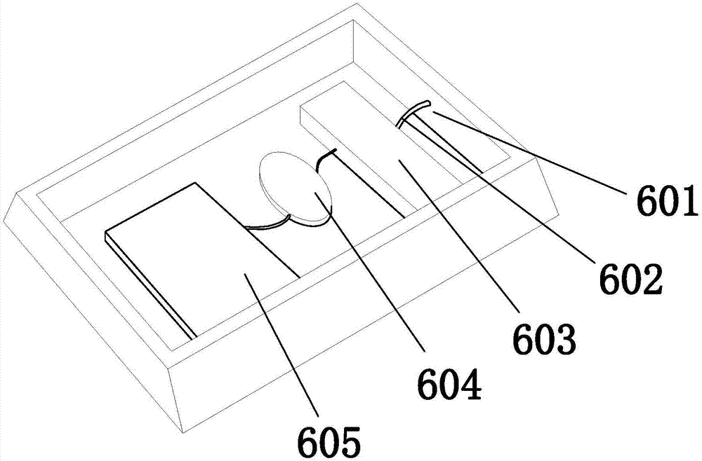
[0018] see Figure 1-Figure 2 , the present invention provides an electronic lock: its structure includes a LOGO slot 1, a protective cover 2, a fingerprint reader 3, a fingerprint hole 4, an electronic host 5, a controller 6, a recording hole 7, a latch 8, a door handle 9, The power connector 10, the locker 8 has a rectangular structure and is arranged on the rear end of the electronic host 5 by snap-fitting, the front end of the electronic host 5 is connected to the bottom of the fingerprint reader 3 by fitting, and the The upper end of the middle part of the electronic host 5 is provided with a buckle for movable installation of the controller 6. The surface of the controller 6 is provided with a groove for movable installation of the recording...


PUM


Abstract

The invention discloses an electronic lock, the structure of which comprises a LOGO slot, a protective cover, a fingerprint identifier, a fingerprint hole, an electronic host, a controller, a recording hole, a locker, a door handle, a power connector, a casing, a data line, The display chip, the audio chip, the control chip, and the locker have a rectangular structure and are arranged at the rear end of the electronic host by buckling. The front end of the electronic host is connected to the bottom of the fingerprint reader by fitting. Set up the buckle of the controller. The beneficial effects of the present invention are: the controller provided in the utility model analyzes the sound through the audio chip, and when the sound is confirmed to be the user, the unlocking control is carried out through the control chip, realizing the voice recognition function, greatly improving the functionality, and using more convenient.

Description

technical field [0001] The invention is an electronic lock, which belongs to the field of electronic locks. Background technique [0002] An electronic combination lock is an electronic product that controls the operation of a circuit or a chip (access control system) through a password input, thereby controlling the closing of a mechanical switch and completing the tasks of unlocking and locking. [0003] The prior art discloses an electronic lock with the application number: 201621147249.6, which includes a lock beam, a locking mechanism, and a driving mechanism. The driving mechanism drives the locking mechanism to unlock according to the unlock command signal received by the electronic lock. The electronic lock also includes: at least one The unlocking in-position detection switch and at least one locking in-position detection switch, at least one unlocking in-position detection switch, detect the unlocked position state of the drive mechanism and send a reset command si...

Claims


Application Information

Patent Timeline
Patent Type & Authority Applications(China)
IPC IPC(8): E05B49/00E05B1/00E05B3/00G07C9/00
CPCE05B49/00E05B1/00E05B3/00G07C9/00563
Inventor 曹燕红
Owner GUANGZHOU DANJUE COMM TECH CO LTD
Learn More